background image

– 8 –

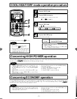
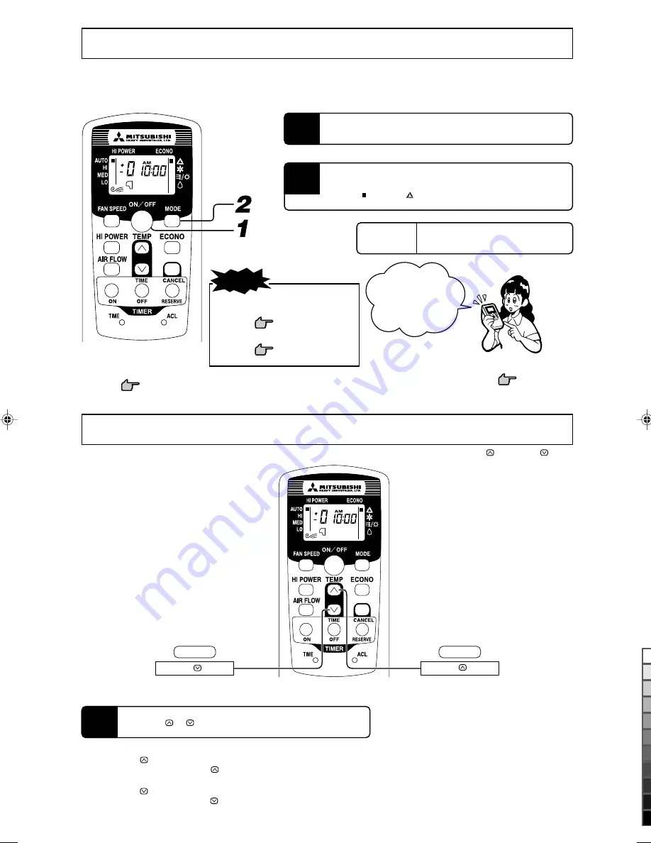
Temperature adjustment during AUTO

Air temperature adjustment is possible even during automatic operation. There are 6 levels of adjustment possible with the 

 button or the 

 button.

1

AUTO mode operation procedure

Automatically selects the operation mode (HEAT, DRY, COOL) depending on the room temperature when switched on.

2

Air flow direction adjustment

procedure. 

 Page 10

WARM

Press the 

 button.

COOL

Press the 

 button.

1

When a change in temperature is desired.

Press the 

 or 

 button.

If you don’t want the AUTO mode programme, change to
HEAT, DRY or COOL instead of AUTO.

 Page 9

AUTO mode can be
operated by simply
pressing the ON/OFF
button.

To stop:

Press the ON/OFF button.

Each time the 

 button is pushed, the switch over occurs in the following order –6 

 –5 

 ............ –1 

 ±0 

 +1 ............ +6.

When +6 is indicatored, even if the 

 button is pushed, the indicator does not change.

Each time the 

 button is pushed, the switch over occurs in the following order +6 

 +5 

 ............ +1 

 ±0 

 –1 ............ –6.

When –6 is indicatored, even if the 

 button is pushed, the indicator does not change.

Air is not blown out during the op-
eration.

 Page 17

Simultaneous automatic operation.

 Page 16

Aim the remote control at the air-conditioner.

Press the ON/OFF button.

When the unit is not in AUTO mode:

Press MODE button.

Move the [

 mark] to the 

(Auto) position.

NOTE

RJH012A011_Eng

10/19/05, 1:47 PM

8

Black

Summary of Contents for STM25ZE

Page 1: ...omplies with EMC Directive 89 336 EEC LV RJH012A011 EN ENGLISH USER S MANUAL AIR CONDITIONER ...

Page 2: ... remote control 7 AUTO mode operation procedure 8 Temperature adjustment during AUTO 8 COOL HEAT DRY mode operation procedure 9 Concerning HIGH POWER operation 9 Concerning ECONOMY operation 9 Air flow direction adjustment procedure 10 About FAN SPEED 10 OFF TIMER operation procedure 11 ON TIMER operation procedure 11 PROGRAM TIMER operation procedure 12 About TIMER operation 12 Present time setti...

Page 3: ... has been properly earthed Earth cables should never be connected to a gas pipe municipal water pipe light ning conductor or telephone earth cable Incorrect installation of the earth cable may produce an electric shock Depending on the place of installation a circuit breaker may be necessary If you don t fit a circuit breaker you may cause an electric shock Do not install near places where inflamm...

Page 4: ...down and cause personal injury Stand firmly on a stepladder or other stable object when removing the inlet grill and filters Failure to observe this may result in injury through insecure objects toppling over Consult your dealer for repairs to the system Wrong repairs could cause an electric shock fire etc If you notice anything abnormal smell of burning etc stop the system turn off the power swit...

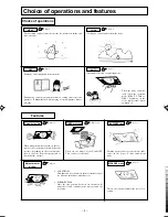
Page 5: ...me position the next time Page 8 Automatic selection of operating mode The Auto mode automati cally selects the operation mode HEAT COOL or DRY depending on the room temperature when switched on Adjustment of airflow AUTO Page 9 Cooling by extracting heat from the room COOL Choice of operations Page 9 The unit draws in heat from the outside air transfers it inside and heats the room HEAT Page 9 Dr...

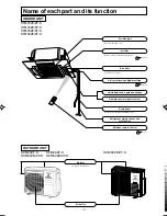
Page 6: ...trol Page 7 Drain hose Drains water from the dehumidified air Air inlet grill Draws in the indoor air Remote control signal receiver Air outlet Air blows out of here Unit indication operation section Air filter Removes dust or dirt from the inlet air Page 15 Refrigerant piping connection electric flex Air flow direction adjustment flap Page 10 SCM40ZF S SCM45ZD ZF S SCM48ZF S SCM60ZD ZF S ...

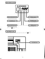
Page 7: ...age 13 Unit ON OFF button Remote control signal receiver Unit ON OFF button RUN HOT KEEP light green Illuminates during operation Blinks at air flow stop due to the HOT KEEP Page 17 ECONO light orange Illuminates during ECONOMY operation TIMER light yellow Illuminates during TIMER operation HI POWER light green Illuminates during HIGH POWER operation ...

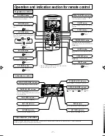
Page 8: ...MER time CANCEL button This button cancels the ON timer and OFF timer RESERVE button This button sets the present time and TIMER time Indication section TEMPERATURE indicator Indicates set temperature Does not indicate temperature when operation mode is on AUTO FAN SPEED indicator Indicates set air flow rate with lamp AIR FLOW indicator Shows selected flap mode HIGH POWER MODE indicator Indicates ...

Page 9: ...HEAT DRY or COOL instead of AUTO Page 9 AUTO mode can be operated by simply pressing the ON OFF button To stop Press the ON OFF button Each time the button is pushed the switch over occurs in the following order 6 5 1 0 1 6 When 6 is indicatored even if the button is pushed the indicator does not change Each time the button is pushed the switch over occurs in the following order 6 5 1 0 1 6 When 6...

Page 10: ...n order to avoid an excessive cooling or heating The unit operates 1 5 C higher than the setting temperature for the weak wind capacity during cooling or 2 5 C lower than that during heating A message is displayed on the remote control The wind capacity display is erased NOTE During the HIGH POWER operation the room temperature is not controlled When it causes an excessive cooling or heating press...

Page 11: ...oner when heating or cooling When changing FAN SPEED from HI to LO the sound of refrigerant flowing may be heard NOTE Air scroll Flap moves up and down continuously If the room temperature control thermostat switches to the heating mode or if the defrosting operation is on the blow flap changes automatically to a horizontal position If the heating operation has just started and the room temperatur...

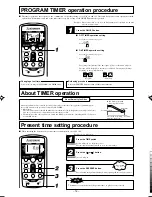
Page 12: ...0 AM 1 10 Each time the button is pressed the indicator is switched in the order of AM 0 00 PM 11 50 PM 11 40 PM 11 00 PM 10 50 Set at AM 8 00 Press the RESERVE button The indication changes from blinking to steady lighting and the setting is complete The timer light yellow is on Operation starts 5 to 60 minutes before the set time The TIMER light goes out at the set time Example You wish it to st...

Page 13: ...ture is checked 60 minutes before the timer is at ON Depending on the temperature at that time the operation starts 5 to 60 minutes before the timer is at ON The Amenity facility only functions for COOL and HEAT operation mode including AUTO It does not work for DRY mode In COOL operation Stop Operation starts Check the room temp 60 mins in advance Set time Operation 2 Present time setting procedu...

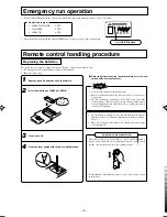
Page 14: ...tery causing the remote control to malfunction Remove back lid and take out old batteries Insert new batteries SUM 4 or R03x2 Close back lid When the indicator shows any abnormal condition press the reset switch with the tip of a ballpoint pen 1 2 3 Attention to the and marks Emergency run operation The unit ON OFF button on the unit operates ON OFF temporarily when the remote control is not used ...

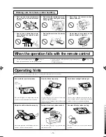
Page 15: ... block the air flow and cause less efficient operation Please request cleaning of the air filter from special contractor Don t go near high temperature places such as an electric carpet or stove Adjust the airflow direction properly Adjust the up down and left right airflow to ensure a steady room temperature Do not place heavy objects on the remote control or step on it Warning note for remote co...

Page 16: ...he indoor and outdoor units NOTE Cooling heating is affected by an air filter clogged up with dust etc and the operation noise becomes louder It may also use extra electricity Please clean the air filter at appropriate intervals 1 2 Remove batteries from the remote control Clean both the indoor and outdoor units Clean and reinstall the air filters Set the temperature setting for approximately a ha...

Page 17: ...ing of oil Malfunctioning due to corrosion may occur if the unit is installed in a spa where sulfide gases are generated or in a seaside resort exposed to sea breezes Contact your dealer The air conditioner and remote control must be at least 1 metre away from a TV set or radio Drain the dehumidified liquid from the indoor unit into a spot that drains well About the Multiple Air conditioner Simult...

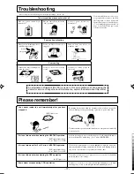
Page 18: ...t restart the unit immediately after you have stopped it RUN light is on Not operating Air is not blown out when starting the HEATING operation RUN light blinks slowly 1 5 sec ON 0 5 sec OFF Air flow has stopped to prevent blowing out of cold air until the indoor heat exchanger has warmed up 2 to 5 min HOT KEEP Air is not blown out for 5 to 10 min at HEATING operation RUN light blinks slowly 1 5 s...

Page 19: ...he sound when operation of another indoor unit is stopped Sometimes a Shooooo sound might come for a short time from the unit that is turned off If one unit is operating in COOL mode while another is in operating in HEAT or any other different operation mode FAN mode operation will be implemented Individual operation modes need to be matched FAN operation will be performed even if COOL DRY or HEAT...

Page 20: ...18 to 32 C SCM40 48 80ZF S Below approximately 80 The long term use of the unit with a humidity level Inside humidity exceeding 80 may result in condensation forming on the surface of the indoor unit leading to water drips Characteristics of HEAT mode operation Mechanism and capacity of HEAT mode operation Mechanism The unit draws in heat from the cold outside air transfers it indoors and heats th...

Page 21: ...scharge pipe sensor closed service valve 6 time flash Error of signal transmission Defective power supply Broken signal wire defective in outdoor unit boards Discharge pipe sensor error Broken discharge pipe sensor wire poor connector connection Suction pipe sensor error Broken suction pipe sensor wire poor connector connection Broken power transistor sensor wire poor connector connection Power tr...

Page 22: ......

Reviews: