-
129
-
'13 • P
A
C-T
-197
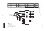
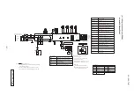
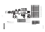
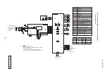
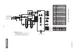
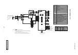
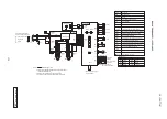
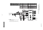
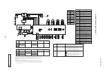
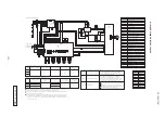
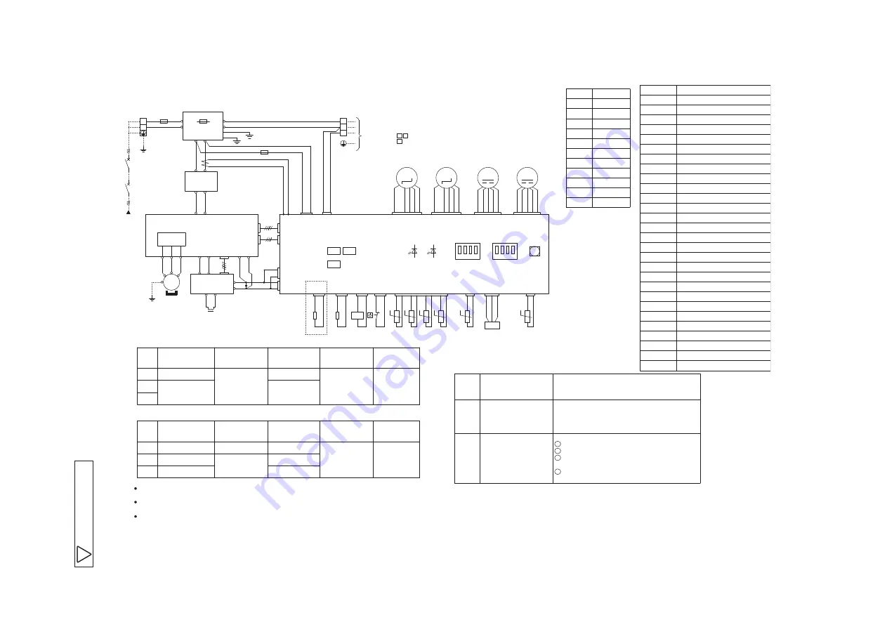
Models FDC100VNX,
125VNX,
140VNX
A
P
C
A
0
0
1
Z
5
7
0
SW3-3,4
SW3-2
SW3-1
Model
125
26
23
φ
1.6mm x 3
φ
1.6
Model
125
29
31
φ
1.6mm x 3
φ
1.6
140
140
30
30
8
5.5
100
24
25
100
25
24
5.5
52X3
Auxilliary relay
(
for CH
)
52X1
Expansion valve for heating
Current sensor
CT
SM2
Crankcase heater
CH
Fan motor
FM01
THo-D
Connector
Terminal block
TB
High pressure switch
63H1
Thermistor
(
Outdoor air temp.
)
THo-A
Compressor motor
CM
Low pressure sensor
LPT
THo-P
THo-S
Expansion valve for cooling
SM1
Solenoid valve for 4 way valve
20S
Fuse
F
THo-R1,2
CnA
~
Z
SW3,5
LED1
SW1
LED2
DM
L
Diode module
Indication lamp
(
GREEN
)
Local setting switch
Pump down switch
Reactor
Auxilliary relay
(
for 20S
)
Thermistor
(
Discharge pipe temp.
)
Thermistor
(
Heat exchanger pipe temp.
)
Thermistor
(
Suction pipe temp.
)
Thermistor
(
IPM
)
Indication lamp
(
RED
)
Color
RD
Mark
Orange
OR
Yellow
/
Green
Y
/
GN
Black
BK
Blue
BL
Gray
GR
Pink
P
Brown
BR
Yellow
Y
White
WH
Red
Local setting switch SW3
(
Set up at shipment OFF
)
Snow guard fan control
Defrost control change
Trial operation
becomes below the freezing point.
2
1
3
is finished.
4
Method of trial operation
Be sure to turn OFF SW3-3 after the trial operation
Trial operation can be performed by using SW3-3,4.
in a very snowy country, set this switch to ON.
the compressor is not runnning when the unit is used
when outdoor temperature falls to 3
℃
or lower and
fan will run for 30 seconds in every 10 minutes,
When this switch is turned ON, the outdoor unit
turned ON in the area where outside temperature
by turning ON this switch. This switch should be
The defrosting operation interval becomes shorter
Power cable, indoor-outdoor connecting wires
MAX over current
Power cable size
(
A
)
Power cable length
(
m
)
indoor-outdoor
wire size x number
Earth wire size
(
mm
)
※
At the connection with the duct type indoor unit.
MAX over current
Power cable size
(
mm
)
2
(
mm
)
2
(
A
)
Power cable length
(
m
)
indoor-outdoor
wire size x number
Earth wire size
(
mm
)
The specifications shown in the above table are for units without heaters. For units with heaters, refer
to the installation instructions or the construction instructions of the indoor unit.
Switchgear of Circuit breaker capacity which is calculated from MAX. over current should be chosen
along the regulations in each country.
The cable specifications are based on the assumption that a metal or plastic conduit is used with no
more than three cables contained in a conduit and a voltage drop is 2%. For an installation falling
outside of these conditions, please follow the internal cabling regulations. Adapt it to the regulation
in effect in each country.
Description
Item
Green
GN
Intelligent power module
IPM
Compressor will be in the operation when SW3-3 is ON.
Cooling trial operation will be performed when SW3-4 is OFF,
and heating trial operation when SW3-4 is ON.
Drain pan heater
DH
52X2
Auxilliary relay
(
for DH
)
POWER SOURCE 1
~
220
ー
240V 50Hz
/
1
~
220V 60Hz
TB
WH
RD
N
L1
CNI3
CNI1
CH
BR
BR
CONTROL
CNW
WH
RD
F
(
30A
)
CNW2
WH
BL
POWER WIRES
SIGNAL WIRE
TO INDOOR UNIT
TB
RD
3
1
2
3
1
2
CNFAN1
CNEEV2
CNEEV1
THo-D
63H1
BK
BK
THo-R1
BK
BK
BK
BK
LED2
LED1
OFF
1
3
2
SW3
4
ON
THo-A
THo-S
THo-P
RD
RD
Y
BK
Y
BK
LPT
(
WH
)
WH
BK
RD
SW1
OFF
3
SW5
1 2
4
ON
OR
6
6
RD
2
4 3
1
Y
OR
BL
WH
7
WH
5 4 1
BL
BR
RD
FMO1
Y
/
GN
WH
t°
t°
t°
t°
t°
20S
BL
BL
CNPS
CNIP
(
Y
)
CNTH
(
WH
)
CNH
(
BR
)
CNR
CNS
(
RD
)
(
WH
)
52X3
52X1
(
WH
)
(
RD
)
(
WH
)
(
OR
)
(
BK
)
(
WH
)
(
WH
)
THo-R2
BK
BK
t°
L1o
No
F
(
8A
)
L1i
Ni
1
2
DM
+
-
N1
P1
CNI4
CNI2
(
WH
)
(
WH
)
CNA1
CNA2
(
WH
)
(
WH
)
N2
P
N2
P2
CNACT1
(
WH
)
RD
BL
WH
P
N2
+
-
L1
L2
A
/
F MODULE
RD
BL
BK
RD
BL
RD
BL
RD
BL
RD
WH
RD
BL
BL
BL
[ ]
(
RD
)
CNB
GN
E1
GN
E
L
U
V
W
U
V
W
PWB1
F
(
4A
)
DH
WH
WH
CNF
(
BK
)
Optional
CNFAN2
OR
6
7
WH
5 4 1
BL
BR
RD
FMO2
(
WH
)
52X2
NOISE FILTER
PWB3
PWB2
+
I P M
INVERTER
CT
CM
3
~
MS
M
6
RD
2
4 3
1
Y
OR
BL
WH
M
M
SM2
SM1
M
GN
Summary of Contents for V Multi 100VNX
Page 98: ... 97 13 PAC T 197 Models FDT100VF1 125VF 140VF H H H H H C B A F G D G PJF000Z285 A ...
Page 101: ... 100 13 PAC T 197 Models FDEN60VF 71VF1 C2 C1 A B A B D C1 C2 C1 C2 E G F C PFA003Z817 ...
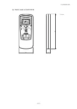
Page 116: ... 115 13 PAC T 197 b Wireless remote control RCN E1R 60 17 150 Unit mm ...
Page 291: ... 290 13 PAC T 197 261 12 PAC T 173 ー K ...
Page 590: ... 589 13 PAC T 197 3 8 SUPER LINK E BOARD SC ADNA E F ...
Page 591: ... 590 13 PAC T 197 ...

