-
158
-
'13 • P
A
C-T
-197
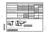
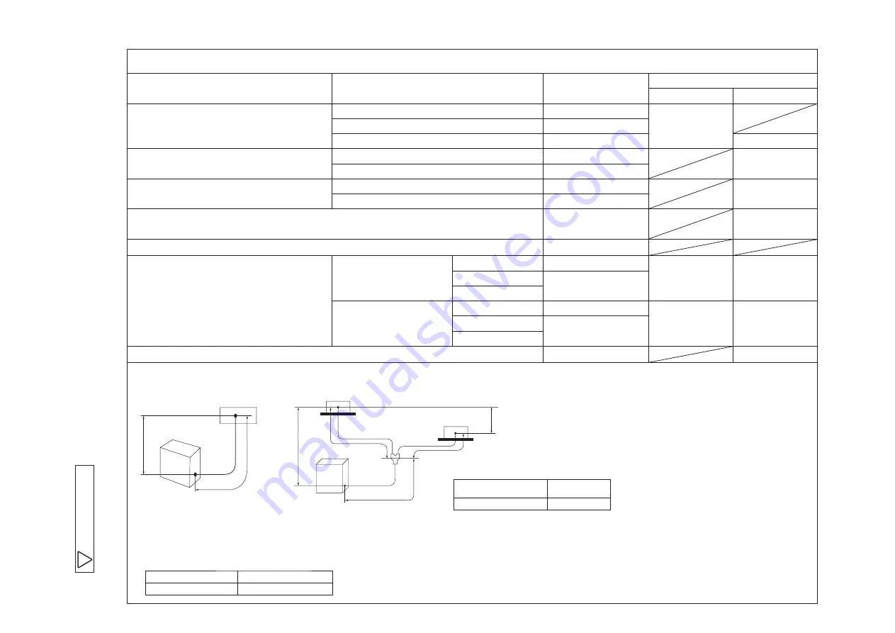
Limitation on unit and piping installation - single, twin.
Descriptions
Models for outdoor unit
Dimensional limitations
Marks appearing in the drawing
Single type
Twin type
One-way pipe length
40 · 50 · 60
<
=
30m
L
71
<
=
50m
100 · 125 · 140
<
=
100m
L + L1 + L2
Main pipe length
71
<
=
20m
L
100 · 125 · 140
<
=
100m
One-way pipe length after first branching point
71
<
=
50m
L1, L2
100 · 125 · 140
<
=
30m
Difference of pipe length after first branching point
<
=
10m
L1 - L2
L2 - L1
Total pipe length after the second branching point
<
=
15m
Elevation difference between indoor and outdoor unit
When outdoor unit is
positioned higher
40 · 50 · 60
<
=
20m
H
H
71
<
=
30m
100 · 125 · 140
When outdoor unit is
positioned lower
40 · 50 · 60
<
=
20m
H
H
71
<
=
15m
100 · 125 · 140
Elevation difference among indoor units
<
=
0.5m
h
H
L
Outdoor unit
Indoor unit
Indoor unit
Single type
Twin type
Outdoor unit
Indoor unit
H
L1
L2
h
L(riser)
71 · 100 · 125 · 140
Twin type
Model for
outdoor units
Branch piping
set (option)
DIS-WA1
(1) A riser pipe must be part of the main.
A branching pipe set should be installed horizontally at point as close to an indoor unit as possible.
(2) Reduce refrigerant amount by according to table below from the factory charge when refrigerant piping is shorter than 3m.
Model for outdoor units
71 · 100 · 125 · 140
Refrigerant to be reduced
1.0 kg
C
P
JF
0
0
0
Z
1
9
5
Summary of Contents for V Multi 100VNX
Page 98: ... 97 13 PAC T 197 Models FDT100VF1 125VF 140VF H H H H H C B A F G D G PJF000Z285 A ...
Page 101: ... 100 13 PAC T 197 Models FDEN60VF 71VF1 C2 C1 A B A B D C1 C2 C1 C2 E G F C PFA003Z817 ...
Page 116: ... 115 13 PAC T 197 b Wireless remote control RCN E1R 60 17 150 Unit mm ...
Page 291: ... 290 13 PAC T 197 261 12 PAC T 173 ー K ...
Page 590: ... 589 13 PAC T 197 3 8 SUPER LINK E BOARD SC ADNA E F ...
Page 591: ... 590 13 PAC T 197 ...

