-
243
-
'13 • PAC-T-197
④
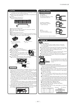
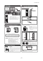
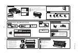
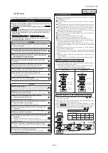
Refrigerant piping
Caution
●
Use the new refrigerant pipe.
When re-using the existing pipe system for R22 or R407C, pay attention to the following
items.
・
Change the flare nuts with the attached ones (JIS category 2), and reprocess the flare
parts.
・
Do not use thin-walled pipes.
●
Use phosphorus deoxidized copper alloy seamless pipe (C1220T specified in JIS
H3300) for refrigeration pipe installation.
In addition, make sure there is no damage both inside and outside of the pipe, and no
harmful substances such as sulfur, oxide, dust or a contaminant stuck on the pipes.
●
Do not use any refrigerant other than R410A.
Using other refrigerant except R410A (R22 etc.) may degrade inside refrigeration oil.
And if air getting into refrigerant circuit, it may cause anomaously high pres and may
result in burst, etc.
●
Store the copper pipes indoors and seal the both end of them until they are brazed in
order to avoid any dust, dirt or water getting into pipe. Otherwise it will cause degrada-
tion of refrigeration oil and compressor breakdown, etc.
●
Use special tools for R410 refrigerant.
Work procedure
1. Remove the flare nuts and flare caps from the pipes of the indoor unit.
※
Make sure to loosen the flare nut by holding the flared male fitting with a spanner
and giving torque to the nut with another spanner in order to avoid unexpected
stress to the copper pipe, and then remove them.
(Gas may come out a little at this time, but it is no anomaly.)
●
Pay attention that the flare nut may pop out.
(Because it is sometimes pressurized in the indoor unit)
2. Make a flare on liquid pipe and gas pipe, and connect the refrigrant pipes to the indoor
unit.
※
Bend the pipe with as big radius as possible and do not bend the pipe repeatedly. In
addition, do not twist and crush the pipes.
※
Do a flare connection as follows:
●
Make sure to loosen the flare nut by holding the flared male fitting with a spanner
and giving torque to the nut with another spanner in order to avoid unexpected
stress to the copper pipe, and then remove them.
●
When fastening the flare nut, align the refrigeration pipe with the center of flare nut,
screw the nut for 3-4 times by hand and then tighten it with a spanner within the
specified torque mentioned in the table below.
Make sure to hold the flared male fitting on the indoor unit side with another spanner
when tightening the nut in order to avoid unexpected stress on the copper pipe.
3. Cover the flare connection part of the indoor unit with attached insulation material after
a gas leakage inspection, and tighten both ends with attached straps.
●
Make sure to insulate both gas pipes and liquid pipes completely.
※
Incomplete insulation may cause dew condensation and dew dropping.
4. Refrigerant is pre-charged in the outdoor unit.
As for the additional refrigerant charge for the indoor unit and piping, refer to the instal-
lation manual attached to the outdoor unit.
Pipe diameter
Tightening torque N·m
φ
6.35
φ
9.52
φ
12.7
φ
15.88
φ
19.05
14 to 18
34 to 42
49 to 61
68 to 82
100 to 120
Strap (Accessory)
Pipe cover (Accessory)
⑤
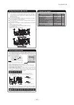
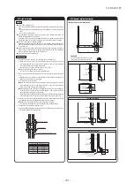
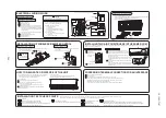
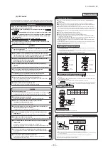
Drain pipe
④
Refrigerant piping (Continued)
●
Electric work must be made by qualified electricians according to the “Engineering
standards concerning electric equipment”, “Extension wiring regulations” and the
electric wiring work manual. Be sure to use dedicated electric circuits.
●
Make sure to use specified wires for wiring, and connect them securely. Clamp the
wires to protect the terminal connection from external force.
●
Make sure to protect the unit with the D-type grounding work.
●
For details of wiring work, refer to the attached electric wiring work manual.
⑥
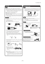
Wire extracting position and wire connecton
⑦
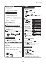
Check list after installation
●
Check the following items after all installation work completed.
Check if;
Expected trouble
Check
The indoor and outdoor units are fixed securely?
Falling, vibration, noise
Inspection for gas leakage is done?
Insufficient capacity
Insulation work is properly done?
Water leakage
Water is drained properly?
Water leakage
Supply voltage is same as mentioned in the model name plate? PCB burnt out, not working at all
There is mis-wiring or mis-connection of piping?
PCB burnt out, not working at all
Earth wiring is connected properly?
Electric shock
Cable size comply with specified size?
PCB burnt out, not working at all
Any obstacle blocks airflow on air inlet and outlet?
Insufficient capacity
Open the air inlet grill by
holding the grips with
both hands and pulling to
this side.
Control box is located as
illustrated at left. Remove
the cover and make
connections.
PGA012D404
WARNING
CAUTION
Drain socket
Procedure
Backward extraction
85
94
Liquid pipe
Gas pipe
Sideward extraction
94
143
Control box position and power cable connection
Control box
Control box
Clamp (for fixing)
Grounding line
Power cable
Clam (For guide)
Terminal block for signal wire
Terminal block for power cable
Clamp (For fixing)
(Unit front)
(Unit right side)
(Unit front)
(Unit right side)
For side extraction (at right and left)
(ø100 knock-out hole)
For backward extraction
(ø100 knock-out hole)
• Do not insert the drain pipe directly in the drain ditch where toxic gases such as
sulffuric gas are produced.
Toxic gas may flow into the room.
• Install the drain pipe properly according to the installation manu And insulate it to
prevent from dew condensation.
Improper installation of drain pipe may cause damage of furniture drainage water
leaked or dew condensation.
Upward bend not allowed
Trap not allowed
Submersion in water not allowed
Decline the pipe lightly.
• Insulate the drain pipe to prevent dewing. (Especially in room and unit)
• Incline the drain pipe downward to the outlet (1/50 – 1/100). Upward bend or trap is
not allowed on the way.
• Use a commercial hard polyvinyl chloride pipe, PV-20, for the drain pipe.
<Use of adhesive agent is prohibited.>
ATTENTION:
1. Connect the drain socket to the drain pipe (PV-20) provided at site and fix the joint with
adhesive tape, or the like.
2. When the pipe provided at site runs through a room, insulate the pipe with a commercial
insulator (Polyethylene foam: Specific gravity 0.03, thickness 15 mm or more) to prevent
dewing.
①
Remove the control box cover (fixed with a screw).
②
Introduce wires in the unit and connect securely on the terminals.
③
Fix each wire with a clamp (for fixing).
④
Install removed parts as they were.
Procedure
• Make sure to pass the power cable through the clamp (for guide).
◆
Pipe and wire extracting position
400
48
93
600
468
Liquid pipe
Gas pipe
Downward extraction
440
Liquid pipe
Gas pipe
61
14
3
30
5
Pipe cover
(For liquid pipe)
(Unit front)
(Unit bottom)
(Unit right side)
Pipe cover
(For gas pipe)
For downward
extraction
(ø100 hole)
The thickness of insulation should be 20mm or more.
ATTENTION:
• Do not cut off the flange at the hole on the
base plate for the downward extraction.
Pipe cover
(Liquid pipe)
Pipe cover
(Gas pipe)
Liquid pipe
Gas pipe
Pipe cover
(For liquid pipe)
Pipe cover
(For gas pipe)
Summary of Contents for V Multi 100VNX
Page 98: ... 97 13 PAC T 197 Models FDT100VF1 125VF 140VF H H H H H C B A F G D G PJF000Z285 A ...
Page 101: ... 100 13 PAC T 197 Models FDEN60VF 71VF1 C2 C1 A B A B D C1 C2 C1 C2 E G F C PFA003Z817 ...
Page 116: ... 115 13 PAC T 197 b Wireless remote control RCN E1R 60 17 150 Unit mm ...
Page 291: ... 290 13 PAC T 197 261 12 PAC T 173 ー K ...
Page 590: ... 589 13 PAC T 197 3 8 SUPER LINK E BOARD SC ADNA E F ...
Page 591: ... 590 13 PAC T 197 ...

