-
316
-
'13 • PAC-T-197
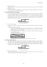
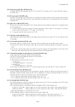
(12) Drain pump control
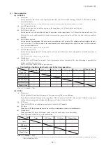
(a) This control is operated when the inverter frequency is other than 0 Hz during the cooling operation and automatic
cooling and dehumidifying operations.
(b) Drain pump ON condition continues for 5 minutes even when it enters the OFF range according to (i) above after turning
the drain pump ON, and then stops. The 5-minute delay continues also in the event of anomalous stop.
(c) The drain pump is operated with the 5-minute delay operation when the compressor is changed from ON to OFF.
(d) Even in conditions other than the above (such as heating, fan, stop, cooling thermostat OFF), the drain pump control is
performed by the drain detection.
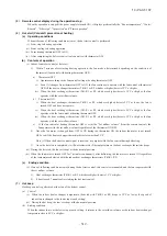
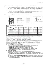
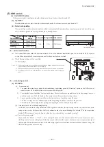
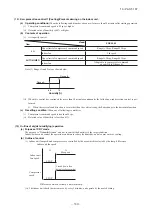
(e) Following settings can be made using the indoor function setting of the wired remote control.
(i)
(ii)
(iii)
(iv)
Note (1) Values in
〔
〕
are for the RC-EX1A model.
ާ
Standard
in cooling & dry
ި
: Drain pump is run during cooling and dry.
ާ
Operate in standard & heating
ި
: Drain pump is run during cooling, dry and heating.
ާ
Operate in heating & fan
ި
: Drain pump is run during cooling, dry, heating and fan.
ާ
Operate in standard & fan
ި
: Drain pump is run during cooling, dry and fan.
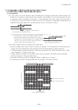
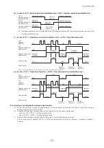
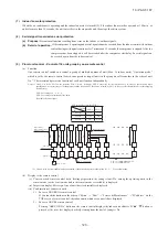
(13) Drain motor (DM) control
(a)
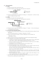
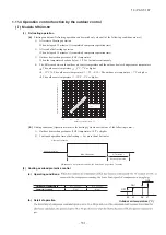
Drain detection switch is turned ON or OFF with the float switch (FS) and the timer.
[
*
1] Drain detection switch is turned “ON” when the float switch “Open” is detected for 3 seconds continuously in the
drain detectable space.
[
*
2] Drain detection switch is turned “OFF” when the float switch “Close” is detected for 10 seconds continuously.
(i) It detects always from 30 seconds after turning the power ON.
1) There is no detection of anomalous draining for 10 seconds after turning the drain pump OFF.
2) Turning the drain detection switch “ON” causes to turn ON the drain pump forcibly.
3) Turning the drain detection switch “OFF” releases the forced drain pump ON condition.
Normal state
[*1]
[*2]
Normal state
Drain detection switch ON
Stop
(1)
Indoor unit operation mode
Control A
Control B
Compressor ON
Compressor OFF
Cooling
Dry
Heating
Fan
(2)
Note (1) Including the stop from the cooling, dehumidifying, fan
and heating, and the anomalous stop
(2) Including the “Fan” operation according to the
mismatch of operation modes
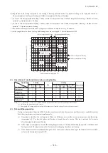
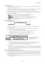
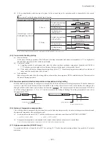
(i) Control A
1) If the float switch detects any anomalous draining condition, the unit stops with the anomalous stop (displays E9)
and the drain pump starts. After detecting the anomalous condition, the drain motor continues to be ON.
2) It keeps operating while the float switch is detecting the anomalous condition.
(ii) Control B
If the float switch detects any anomalous drain condition, the drain motor is turned ON for 5 minutes, and at 10
seconds after the drain motor OFF it checks the float switch. If it is normal, the unit is stopped under the normal
mode or, if there is any anomalous condition, E9 is displayed and the drain motor is turned ON. (The ON condition is
maintained during the drain detection.)
(b)
Indoor unit performs the control A or B depending on each operating condition.
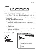
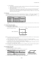
(14) Operation check/drain pump test run operation mode
(a) If the power is turned on by the dip switch (SW7-1) on the indoor PCB when electric power source is supplied, it enters the
mode of operation check/drain pump test run. It is ineffective (prohibited) to change the switch after turning power on.
(b) When the communication with the remote control has been established within 60 seconds after turning power on by the
dip switch (SW7-1) ON, it enters the operation check mode. Unless the remote control communication is established, it
enters the drain pump test run mode.
Note (1) To select the drain pump test run mode, disconnect the remote control connector (CNB) on the indoor PCB to shut down the remote control
communication.
Summary of Contents for V Multi 100VNX
Page 98: ... 97 13 PAC T 197 Models FDT100VF1 125VF 140VF H H H H H C B A F G D G PJF000Z285 A ...
Page 101: ... 100 13 PAC T 197 Models FDEN60VF 71VF1 C2 C1 A B A B D C1 C2 C1 C2 E G F C PFA003Z817 ...
Page 116: ... 115 13 PAC T 197 b Wireless remote control RCN E1R 60 17 150 Unit mm ...
Page 291: ... 290 13 PAC T 197 261 12 PAC T 173 ー K ...
Page 590: ... 589 13 PAC T 197 3 8 SUPER LINK E BOARD SC ADNA E F ...
Page 591: ... 590 13 PAC T 197 ...

