-
362
-
'13 • PAC-T-197
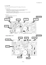
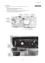
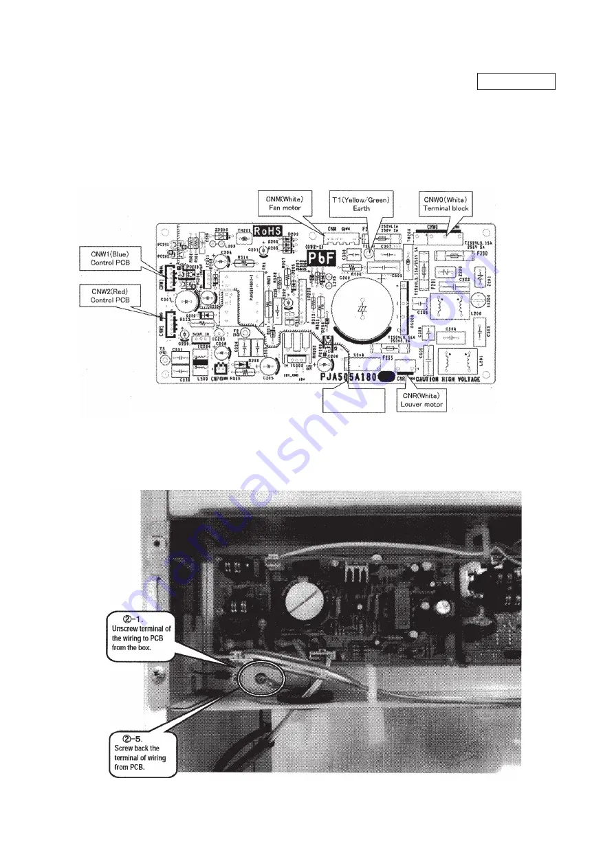
b) Power PCB
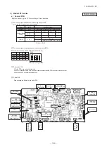
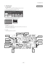
Part number
This PCB is a general PCB. Replace the PCB according to this instruction
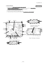
Replace the PCB
1. Unscrew terminal of the wiring(yellow/green) soldered to PCB from the box.
2. Replace the PCB only after all the wirings connected to the conneclor are removed.
3. Fix the board such that it will not pinch any of the wires.
4. Reconnect the wirings to the PCB. Wiring connector color should match with the color of connector of the PCB.
5. Screw back the terminal of wiring of wiring(yellow/green) from PCB(T1) that was removed in 1.
In that case, do not place the crimping part of the wiring under the PCB.
PSB012D953C
Summary of Contents for V Multi 100VNX
Page 98: ... 97 13 PAC T 197 Models FDT100VF1 125VF 140VF H H H H H C B A F G D G PJF000Z285 A ...
Page 101: ... 100 13 PAC T 197 Models FDEN60VF 71VF1 C2 C1 A B A B D C1 C2 C1 C2 E G F C PFA003Z817 ...
Page 116: ... 115 13 PAC T 197 b Wireless remote control RCN E1R 60 17 150 Unit mm ...
Page 291: ... 290 13 PAC T 197 261 12 PAC T 173 ー K ...
Page 590: ... 589 13 PAC T 197 3 8 SUPER LINK E BOARD SC ADNA E F ...
Page 591: ... 590 13 PAC T 197 ...


