-
367
-
'13 • PAC-T-197
(v) Phenomenon observed after shortcircuit, wire breakage on sensor
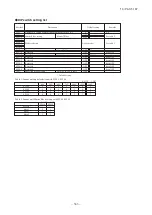
Sensor
Operation
mode
Phenomenon
Shortcircuit
Disconnected wire
Room temperature
sensor
Cooling
Heating
Heat exchanger
sensor
Cooling
Heating
Humidity sensor
Cooling
Heating
■
Humidity sensor operation
Failure mode
Control input circuit resding
Air conditioning system operation
①
②
①②
①
②
Freezing cycle system protection trips and stops the compressor.
circuit
'09•SRK-DB-087D
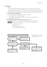
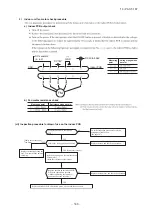
(vi) Checking the indoor electrical equipment
1) Indoor PCB check procedure
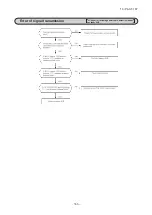
(b) Outdoor unit
Is there voltage between terminal
blocks
①
and
②
? (AC 220/230/240
V)
Indoor electrical components
are normal.
Is the voltage between terminal
blocks
②
and
③
oscillating between
DC 0 and 20V?
Inspect power source
for outdoor unit.
Replace fuse.
Replace indoor PCB.
Is the fuse burnt out? (3.15 A)
NO
YES
YES
NO
YES
NO
2) Indoor unit fan motor check procedure
a) Indoor PCB output check
① ④
⑤
b) Fan motor resistance check
⑥
⑤
④
③
②
①
⑥
⑤
④
③
②
①
FM
I
DC15V
Indoor PCB
DC 308~336V
DC several V
(4~6 V)
CNU
(–)
GND
Blue
Yello
w
White
Black
Red
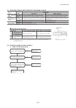
Sensor
Operation
mode
Phenomenon
Shortcircuit
Disconnected wire
Heat exchanger
sensor
Cooling
Heating
Ourdoor air
temperature sensor
Cooling
Heating
Discharge pipe
sensor
All modes
Measuring point
Resistance when normal
① − ③
−
④ − ③
−
Measuring
point
Voltage range when
normal
① − ③
④ − ③
⑤ − ③
Defrosting is performed for 10 minutes at approx. 35 minutes.
Defrosting is performed for 10 minutes at approx. 35 minutes.
k
M
i)
ii)
iii)
Summary of Contents for V Multi 100VNX
Page 98: ... 97 13 PAC T 197 Models FDT100VF1 125VF 140VF H H H H H C B A F G D G PJF000Z285 A ...
Page 101: ... 100 13 PAC T 197 Models FDEN60VF 71VF1 C2 C1 A B A B D C1 C2 C1 C2 E G F C PFA003Z817 ...
Page 116: ... 115 13 PAC T 197 b Wireless remote control RCN E1R 60 17 150 Unit mm ...
Page 291: ... 290 13 PAC T 197 261 12 PAC T 173 ー K ...
Page 590: ... 589 13 PAC T 197 3 8 SUPER LINK E BOARD SC ADNA E F ...
Page 591: ... 590 13 PAC T 197 ...


