-
371
-
'13 • PAC-T-197
(ii)
Model FDC100VNX, 125VNX, 140VNX
2)
Model
FDC100VSX, 125VSX, 140VSX
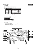
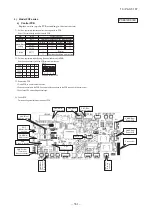
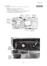
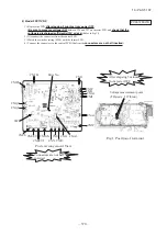
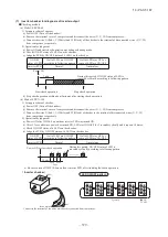
1) Replace the PCB
after elapsing 3 minutes from power OFF
.
(
Be sure to measure voltage (DC)
on both capacitor terminals located in controller
back, and
check that the voltage is discharged sufficiently
.)
2) Disconnect the connectors from the control PCB.
3) Disconnect the white wiring passing through CT1 on the PCB before replacing the PCB.
4) Match the setting switches (SW3-5, JSW) with the former PCB.
5) Tighten up a screw after passing white wiring through CT1 of the changed.
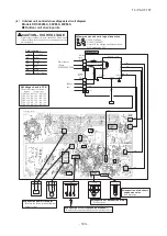
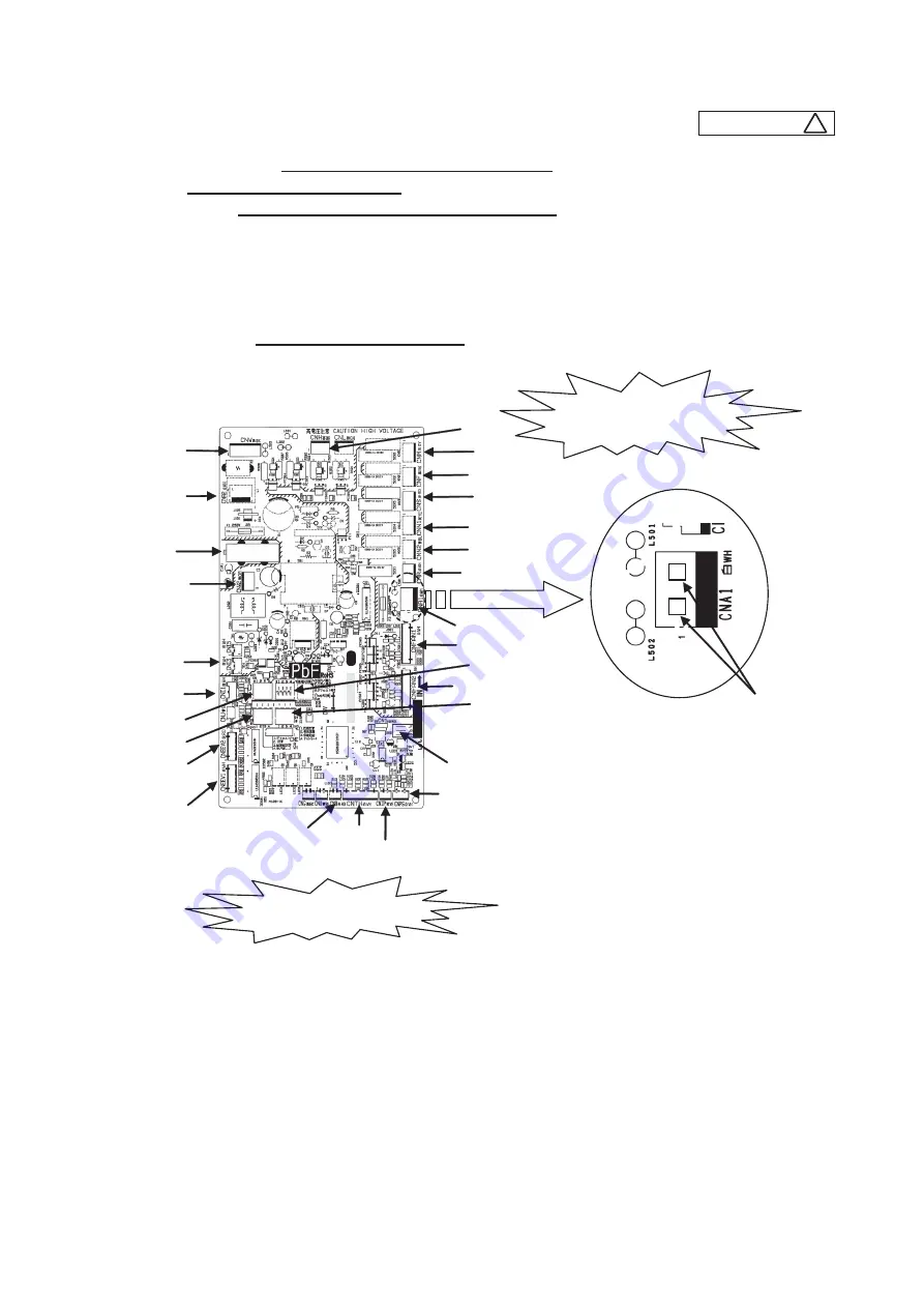
6) Connect the connectors with the control PCB referring to the parts arrangement of Fig.1.
(Confirm the
connectors are not half inserted
.)
PCA012D043
B
After elapsing 3 minutes
from power OFF
Connectors are not half
inserted
Parts Arrangement View
CNA2
CNIP
CNTH
CNPS
CNI1
CNI3
CNA1
CNFAN1
CNEEV2
CNEEV1
CNS
CNR
CNH
CNW
CNW2
JSW
SW5
SW4
SW3
CNB
CT1
P
C
A
5
0
5
A
1
8
7
SW
(
J5-7
)
CNF
CNN1
CNM
CNN2
Fig.1 Enlarged figure of parts location
CNFAN2
Voltage measurement parts
(Pin terminals1-2 of CNA1)
(
-
)
(
+
)
Summary of Contents for V Multi 100VNX
Page 98: ... 97 13 PAC T 197 Models FDT100VF1 125VF 140VF H H H H H C B A F G D G PJF000Z285 A ...
Page 101: ... 100 13 PAC T 197 Models FDEN60VF 71VF1 C2 C1 A B A B D C1 C2 C1 C2 E G F C PFA003Z817 ...
Page 116: ... 115 13 PAC T 197 b Wireless remote control RCN E1R 60 17 150 Unit mm ...
Page 291: ... 290 13 PAC T 197 261 12 PAC T 173 ー K ...
Page 590: ... 589 13 PAC T 197 3 8 SUPER LINK E BOARD SC ADNA E F ...
Page 591: ... 590 13 PAC T 197 ...


