-
379
-
'13 • PAC-T-197
LED
U
V
W
LED1
LED3
LED5
LED2
LED4
LED6
LED1
LED3
LED5
LED2
LED4
LED6
LED1
LED3
LED5
LED2
LED4
LED6
LED1
LED3
LED5
LED2
LED4
LED6
LED1
LED3
LED5
LED2
LED4
LED6
LED1
LED3
LED5
LED2
LED4
LED6
〜
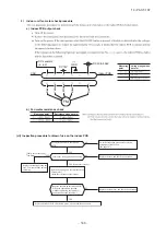
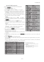
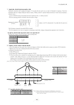
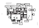
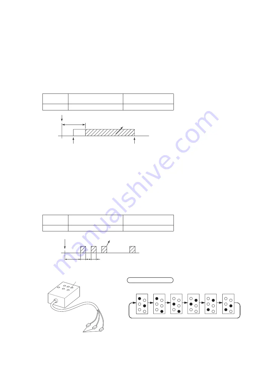
(7) Inverter checker for diagnosis of inverter output
●
Checking method
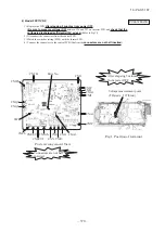
(a) Model: SRC40-60
1) Setup procedure of checker.
a) Power OFF (Turn off the breaker).
b) Remove the terminal cover of compressor and disconnect the wires (U, V, W) from compressor.
c) Connect the wires U (Red) , V (White) and W (Black) of the checker to the terminal of disconnected wires (U, V, W)
from compressor respectively.
2) Operation for judgment.
a) Power ON and start check operation on cooling or heating mode.
b) Check ON/OFF status of 6 LED's on the checker.
c) Judge the PCB by ON/OFF status of 6 LED's on the checker.
d) Stop check operation within about 2minutes after starting check operation.
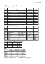
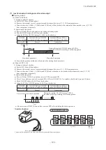
ON/OFF
status of LED
If all of LED are ON/OFF
according to following pattern
If all of LED stay OFF or
some of LED are ON/OFF
Inverter PCB
Normal
Anomalous
ON/OFF
status of LED
If all of LED are ON/OFF
according to following pattern
If all of LED stay OFF or
some of LED are ON/OFF
Inverter PCB
Normal
Anomalous
Power ON
3 min.
15 sec.
5sec.
5sec.
5sec.
Start check operation
Stop check operation
During this period, ON/OFF status of LED is
repeated cyclically according to following pattern
During this period, ON/OFF status of LED is
repeated cyclically according to following pattern
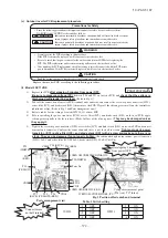
(b) Model: FDC71-140
1) Setup procedure of checker.
a) Power OFF (Turn off the breaker).
b) Remove the terminal cover of compressor and disconnect the wires (U, V, W) from compressor.
c) Connect the wires U (Red) , V (White) and W (Black) of checker to the terminal of disconnected wires (U, V, W)
from compressor respectively.
2) Operation for judgment.
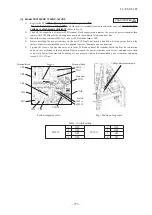
a) Power ON after JSW10-4 on outdoor inverter PCB was turned ON.
b) After 15 seconds since power has turned ON, LED start ON/OFF for 5 seconds cyclically and it repeats 10 times.
c) Check ON/OFF status of 6 LED's on the checker.
d) Judge the PCB by ON/OFF status of 6 LED's on the checker.
e) Be sure to turn off JSW10-4 on outdoor inverter PCB, after finishing the check operation.
Power ON or start check operation
1
2
3
10
Cyclically
●
ON
○
OFF
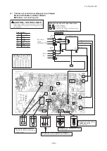
Red
Black
White
Faston terminal
〈
Inverter checker
〉
Connect to the terminal of the wires which are disconnected from compressor.
LED ON/OFF pattern
Summary of Contents for V Multi 100VNX
Page 98: ... 97 13 PAC T 197 Models FDT100VF1 125VF 140VF H H H H H C B A F G D G PJF000Z285 A ...
Page 101: ... 100 13 PAC T 197 Models FDEN60VF 71VF1 C2 C1 A B A B D C1 C2 C1 C2 E G F C PFA003Z817 ...
Page 116: ... 115 13 PAC T 197 b Wireless remote control RCN E1R 60 17 150 Unit mm ...
Page 291: ... 290 13 PAC T 197 261 12 PAC T 173 ー K ...
Page 590: ... 589 13 PAC T 197 3 8 SUPER LINK E BOARD SC ADNA E F ...
Page 591: ... 590 13 PAC T 197 ...


