UNIT PARTS IDENTIFICATION
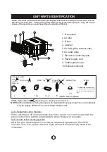
NOTE: The front panel and cabinet may be slightly different according to the models, but the
functions are the same. The following illustration is for explanation purpose only, the actual
shape of the machine you purchased may be slightly different.
NOTE
:All the illustrations in the manual are for explanation purpose only.Your air conditionar
may be slightly different.The actual shape shall prevail.
NOTE: Optional parts( ), depending on model you purchased.
Accessories
(
?
)
Seal
(Used on
drain joint)
1
1
Screw
2
(For >18000Btu/h models only:
Used to fasten the front panel)
2 or 4
( Used to install the drain
tray)
Drain Joint
1 pec
1pec
Drain Tray
Rubber Plug
1or 2
(depend on model you purchased)
(
?
)
(
?
)
or
8
Wooden screw
(optional)(
?
)
5
After the unit has stopped, it can not be restarted operation in the first 3
minutes. This is to protect the unit. Operation will automatically start after
3 minutes.
Wait 3 minutes before resuming operation
If the unit breaks off unexpectedly due to the power cut,it will restart with the
previous function setting automatically when the power resumes.
Auto-Restart(on some models)
1. Front panel
2. Air filter
3. Frame
4. Cabinet
5. Air inlet grille (outdoor side)
6. Air outlet grille
7. Electronic control keypad
8. Power supply cord
9. Control panel cover
10. Remote controller
9
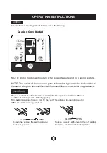
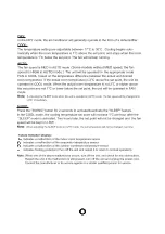
MODE
SLEEP
LED
CLOCK
CANCEL
TIMER
FAN
RESET LOCK
CLOCK
E
ON
OFF
SET TEMP .
FAN SPEED
AUTO
F
SWING
10
Summary of Contents for WRK20MA1
Page 10: ...OPERATING INSTRUCTIONS 7 ...
Page 11: ...8 ...
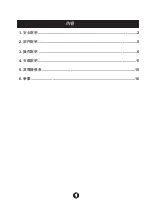
Page 23: ...1 內容 1 安全說明 2 2 部件說明 5 3 操作說明 6 4 安裝說明 11 5 故障檢修表 15 6 參數 16 ...
Page 29: ...7 7 POWER MODE MODE 1 30 1 17 FAN FAN SWING SWING TIMER 24 0 5 10 1 ...
Page 30: ...8 8 17 30 SWING ...
Page 31: ... Note 9 9 ...
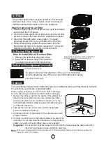
Page 32: ...1 2 1 2 3 4 1 2 3 40 4 10 10 1 2 3 4 T RUBBER PLUG SCREW DRAIN PAN DRAIN OUTLET ...
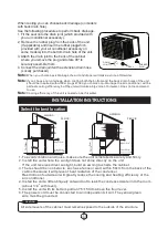
Page 35: ...13 13 1 See Fig 1 2 See Fig 2 4 A B C D 2 1 Fig 3A Fig 3B Fig 3C Fig 3D 2 Fig 4 ...
Page 37: ... 15 15 ...
Page 39: ......

