ACTIVE-ELECTRONIC CONTROL SUSPENSION
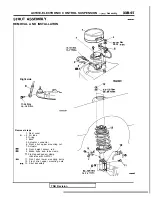
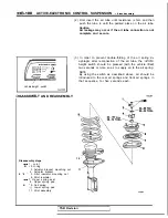
Strut Assembly
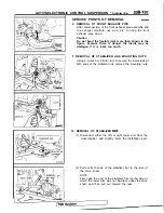
SERVICE POINTS OF REMOVAL
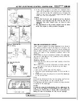
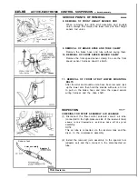
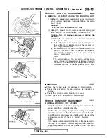
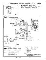
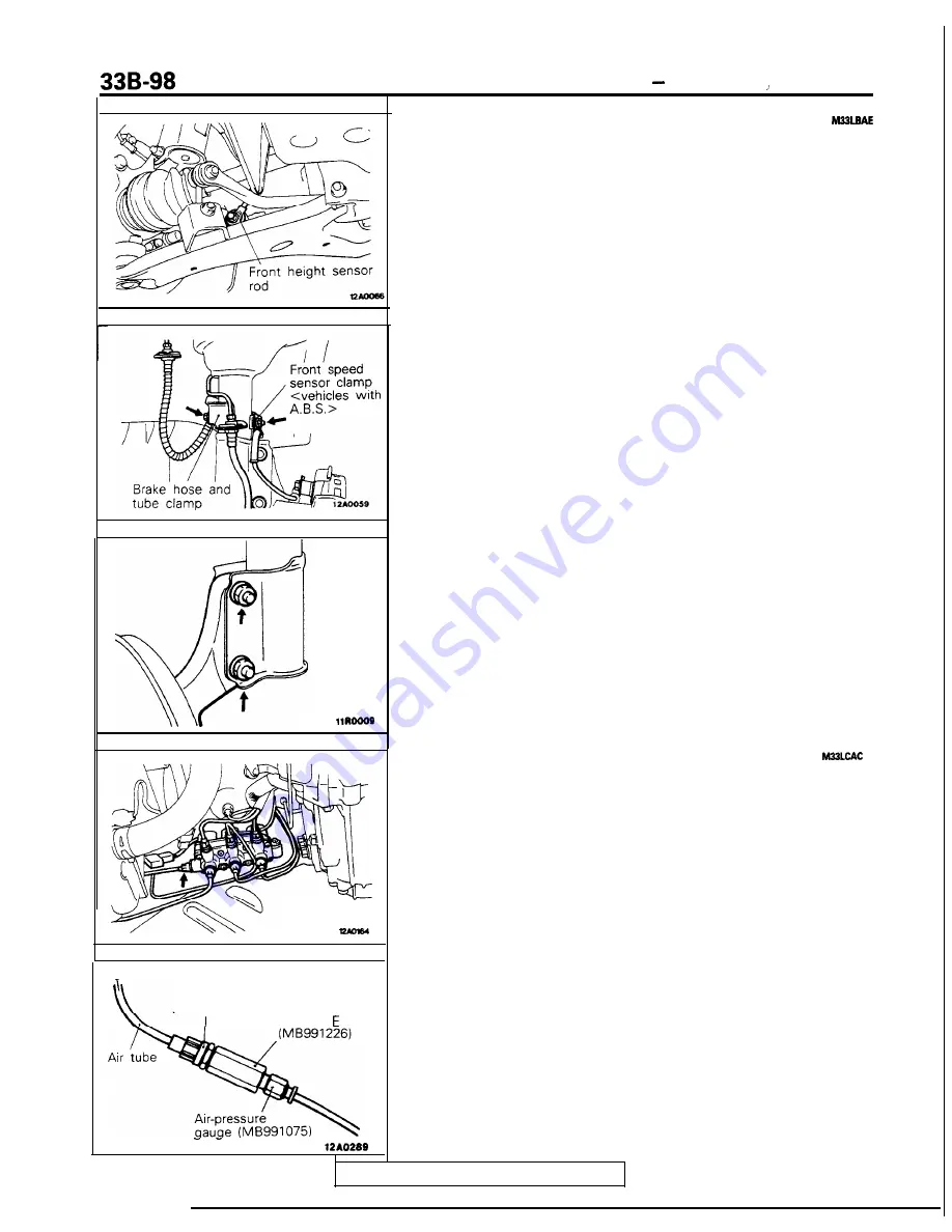
8. REMOVAL OF FRONT HEIGHT SENSOR ROD
When removing the right strut assembly and knuckle
union, always first remove the lower arm and front height
sensor rod union.
, Reserve tank
Joint assembly
Adaptor
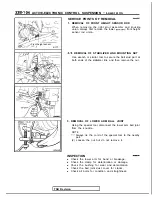
9. REMOVAL OF BRAKE HOSE AND TUBE CLAMP
Remove the brake hose and tube without prying them.
10. REMOVAL OF FRONT SPEED SENSOR CLAMP
Remove the front speed sensor clamp; be sure the front
speed sensor harness doesn’t stretch.
11. REMOVAL OF FRONT STRUT LOWER MOUNTING
BOLTS
After the strut and knuckle union have been removed, jack
up the lower arm, then hold the knuckle with wire, etc. not
to pull on the brake hose and tube, the speed sensor
wiring harness and the drive shaft.
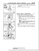
INSPECTION
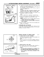
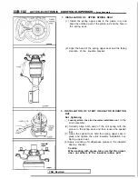
CHECKING FOR STRUT ASSEMBLY AIR LEAKAGE
(1) Disconnect the flow-control solenoid valve’s air tube
(connected to the high-pressure side of the reservoir tank)
s h o w n i n t h e i l l u s t r a t i o n ,
a n d t h e n t a k e o f f t h e j o i n t
assembly.
NOTE
This air tube is connected, via the reservoir tank and the
dryer, to the compressor assembly.
(2) Install the removed joint assembly to the special tool
(adaptor set) and then connect to the disconnected air
tube.
TSB Revision
Summary of Contents for 1989 Galant
Page 2: ......
Page 4: ...00 z NOTES ...
Page 274: ...13 132 NOTE ...
Page 586: ...NOTES ...
Page 650: ...NOTE ...
Page 664: ...NOTES ...
Page 688: ...NOTES ...
Page 690: ......
Page 692: ......
Page 694: ......
Page 696: ......
Page 698: ......
Page 700: ...c ...
Page 702: ......
Page 704: ......
Page 706: ......
Page 708: ......
Page 710: ......
Page 712: ......
Page 714: ......
Page 716: ......
Page 718: ......
Page 720: ......
Page 722: ......
Page 724: ......
Page 729: ...23 23 NOTES ...
Page 860: ...NOTES ...
Page 921: ...NOTES ...
Page 948: ...33B 9 NOTES ...
Page 1121: ...NOTES ...
Page 1200: ...SERVICE BRAKES Brake Pedal 35 79 Lubrication points Part A 14AO256 1 14UOO5l TSB Revision ...
Page 1273: ...NOTES t ...

