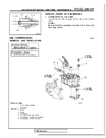
ACTIVE-ELECTRONIC CONTROL SUSPENSION Reserve Tank
Splash
shield
Grommet
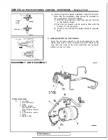
DISASSEMBLY AND REASSEMBLY
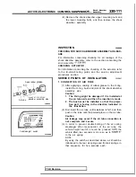
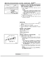
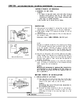
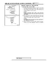
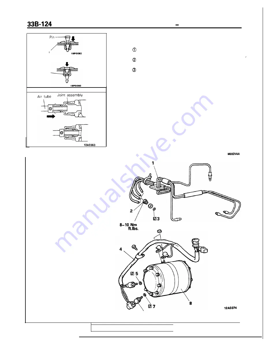
(3) Install the splash shield’s installation clips and the bolt.
Note that the installation clips should be installed by
the procedures described below.
With the pin pulled out, insert the clip into the hole
in the splash shield.
Push the pin inward until its head is flush with the
surface of the grommet.
Check to be sure that the splash shield is securely
fixed.
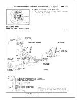
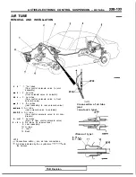
5. INSTALLATION OF AIR TUBES
Push the air tube’ inward to the joint assembly at the
device side until a “click” is heard, and then check to be
sure that the tabs of the joint assembly are securely
affixed to the air tube.
6 - 7
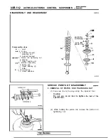
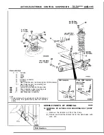
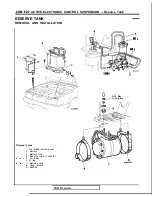
Disassembly steps
l
a
1. Air tubes
2. Joint assembly
3. O-ring
4. Wiring harness
(incorporated with
high pressure switch)
5. O-ring
6. Low pressure switch
7. O-ring
8. Reserve tank
‘6
TSB Revision
I
Summary of Contents for 1989 Galant
Page 2: ......
Page 4: ...00 z NOTES ...
Page 274: ...13 132 NOTE ...
Page 586: ...NOTES ...
Page 650: ...NOTE ...
Page 664: ...NOTES ...
Page 688: ...NOTES ...
Page 690: ......
Page 692: ......
Page 694: ......
Page 696: ......
Page 698: ......
Page 700: ...c ...
Page 702: ......
Page 704: ......
Page 706: ......
Page 708: ......
Page 710: ......
Page 712: ......
Page 714: ......
Page 716: ......
Page 718: ......
Page 720: ......
Page 722: ......
Page 724: ......
Page 729: ...23 23 NOTES ...
Page 860: ...NOTES ...
Page 921: ...NOTES ...
Page 948: ...33B 9 NOTES ...
Page 1121: ...NOTES ...
Page 1200: ...SERVICE BRAKES Brake Pedal 35 79 Lubrication points Part A 14AO256 1 14UOO5l TSB Revision ...
Page 1273: ...NOTES t ...

