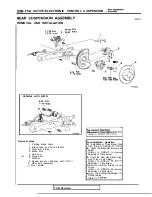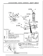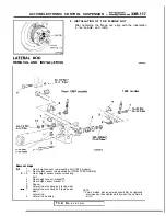
ACTIVE-ELECTRONIC CONTROL SUSPENSION
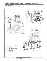
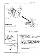
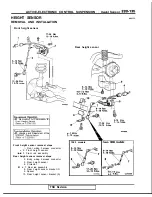
7-11 Nm
4-6 Nm
3 - 4
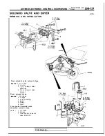
Pre-removal Operation
I
l
Removal of Trunk Room Side
(Refer to GROUP
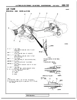
Air tube
Rear solenoid valve removal steps
1 . A i r t u b e s
2. O-rings
8. Rear solenoid valve assembly
9. Rear solenoid valve bracket
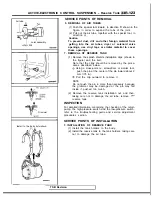
SERVICE POINTS OF REMOVAL
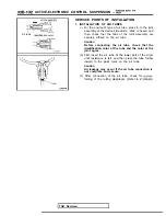
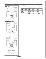
1. REMOVAL OF AIR TUBES
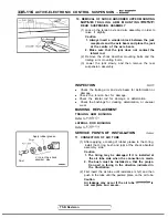
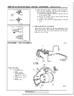
(1) Push the special tool inward,
in direction shown in the
figure, in order to expand the tabs
of the joint.
(2) Pull out the air tube, together with the special
in
direction
Caution
In order to prevent dust, dirt and other foreign
material from getting into the air tube, solenoid
valve and dryer openings. Cover these openings
with vinyl tape or similar material.
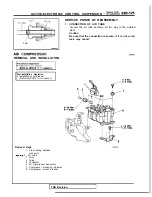
(3)
For
the air tube at the lower part of the dryer,
l o o s e n
Hold to
prevent
turning.
the joint, and then pull off.
NOTE
When loosening the joint, use a spanner at the
hexagonal part of the joint installation part so as to
prevent it from turning.
Joint
TSB Revision
Summary of Contents for 1989 Galant
Page 2: ......
Page 4: ...00 z NOTES ...
Page 274: ...13 132 NOTE ...
Page 586: ...NOTES ...
Page 650: ...NOTE ...
Page 664: ...NOTES ...
Page 688: ...NOTES ...
Page 690: ......
Page 692: ......
Page 694: ......
Page 696: ......
Page 698: ......
Page 700: ...c ...
Page 702: ......
Page 704: ......
Page 706: ......
Page 708: ......
Page 710: ......
Page 712: ......
Page 714: ......
Page 716: ......
Page 718: ......
Page 720: ......
Page 722: ......
Page 724: ......
Page 729: ...23 23 NOTES ...
Page 860: ...NOTES ...
Page 921: ...NOTES ...
Page 948: ...33B 9 NOTES ...
Page 1121: ...NOTES ...
Page 1200: ...SERVICE BRAKES Brake Pedal 35 79 Lubrication points Part A 14AO256 1 14UOO5l TSB Revision ...
Page 1273: ...NOTES t ...

