INTAKE AND EXHAUST
Intake Manifold
VALVE>
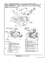
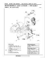
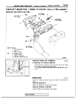
INTAKE MANIFOLD
VALVE> <Up to 1992 models>
AND INSTALLATION
4-6
N m
4-6
‘Nm
3 - 4
Removal steps
Air intake hose
2. Connection for accelerator cable
l
+ 3. Connection for radiator upper hose
4. Connection for water by-pass hose
5. Water hose
6. Connection for heater hose
7. Connection for brake booster vacuum
hose
8. Connection for
high pressure hose
9. O-ring
10. Connection for fuel return hose
Connection for vacuum hoses
12. Vacuum pipe
13.
hose
14. Connection for control harness
4-6
N m
3 - 4
Pre-removal Operation
l
Draining of Engine Coolant
(Refer to GROUP
Service.)
Post-installation Operation
l
Filling of Engine Coolant
(Refer to GROUP
Service.)
l
Adjustment of Accelerator Cable
(Refer to GROUP
Con-
trol.)
l
inspection of Fuel Pressure
(Refer to GROUP
Inspection of
Components.)
TSB
Revision
Summary of Contents for 1989 Galant
Page 2: ......
Page 4: ...00 z NOTES ...
Page 274: ...13 132 NOTE ...
Page 586: ...NOTES ...
Page 650: ...NOTE ...
Page 664: ...NOTES ...
Page 688: ...NOTES ...
Page 690: ......
Page 692: ......
Page 694: ......
Page 696: ......
Page 698: ......
Page 700: ...c ...
Page 702: ......
Page 704: ......
Page 706: ......
Page 708: ......
Page 710: ......
Page 712: ......
Page 714: ......
Page 716: ......
Page 718: ......
Page 720: ......
Page 722: ......
Page 724: ......
Page 729: ...23 23 NOTES ...
Page 860: ...NOTES ...
Page 921: ...NOTES ...
Page 948: ...33B 9 NOTES ...
Page 1121: ...NOTES ...
Page 1200: ...SERVICE BRAKES Brake Pedal 35 79 Lubrication points Part A 14AO256 1 14UOO5l TSB Revision ...
Page 1273: ...NOTES t ...

