REAR AXLE
Axle Shaft
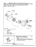
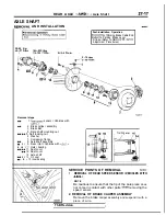
AXLE SHAFT
AND INSTALLATION
55-65 Nm
I
116-159
I
36-43
Post-installation Operation
of Parking Brake Cable End
Parking Brake Lever
Stroke (Refer to GROUP
Adjustment Procedures.)
9-14
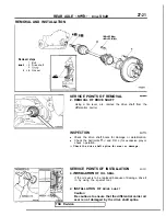
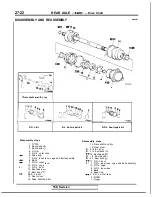
Removal steps
1.
sensor <Vehicles with
2. Brake caliper assembly
3. Brake disc
4. Drive shaft mounting nut
5. Self locking nut
6. Washer
7. Companion flange
8. Axle shaft assembly
l
+ 9. Rear rotor <Vehicles with
l
e
l
+
Outer bearing
11. Dust cover
12. Dust cover
13. Axle shaft
l
4 14. Oil seal
l
+ 15. inner bearing
Trailing
arm
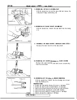
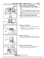
SERVICE POINTS OF REMOVAL
1. REMOVAL OF REAR SPEED SENSOR <VEHICLES WITH
NOTE
Be cautious to ensure that the tip of the pole piece
does
not come in contact with other parts
removing the
speed sensor.
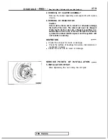
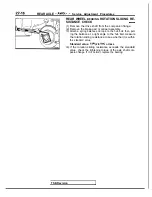
2. REMOVAL OF BRAKE CALIPER ASSEMBLY
Remove the brake
caliper assembly and suspend it with a
piece of wire.
I
TSB Revision
I
Summary of Contents for 1989 Galant
Page 2: ......
Page 4: ...00 z NOTES ...
Page 274: ...13 132 NOTE ...
Page 586: ...NOTES ...
Page 650: ...NOTE ...
Page 664: ...NOTES ...
Page 688: ...NOTES ...
Page 690: ......
Page 692: ......
Page 694: ......
Page 696: ......
Page 698: ......
Page 700: ...c ...
Page 702: ......
Page 704: ......
Page 706: ......
Page 708: ......
Page 710: ......
Page 712: ......
Page 714: ......
Page 716: ......
Page 718: ......
Page 720: ......
Page 722: ......
Page 724: ......
Page 729: ...23 23 NOTES ...
Page 860: ...NOTES ...
Page 921: ...NOTES ...
Page 948: ...33B 9 NOTES ...
Page 1121: ...NOTES ...
Page 1200: ...SERVICE BRAKES Brake Pedal 35 79 Lubrication points Part A 14AO256 1 14UOO5l TSB Revision ...
Page 1273: ...NOTES t ...

