background image

2408

f & 2404f PROFIBUS Communications Handbook                                                                         The Windows Configurator

2408

f and 2404f PROFIBUS Communications Handbook                                                                                                        5-1

CHAPTER 5   THE WINDOWS CONFIGURATOR

The Windows Configurator creates a ‘GSD’ file which provides a simple way of mapping device parameters into the PLC or
supervisory package input/output registers.  The GSD file is imported into a PROFIBUS Master which in turn produces a file
that is downloaded into the PLC or supervisory package.  It works on the ‘drag and drop’ principle by clicking on parameters
within lists (which correspond to the parameter lists in the controller) and dragging the chosen parameter to input or output
windows.

I

NSTALLATION

The program will run on Windows 3.1, Windows 95 or Windows NT.

To install the program, place the Eurotherm PROFIBUS-DP Support Disc in your drive and run A:\SETUP.EXE from the
program manager or Windows explorer.
Follow the on-screen prompts to install the configurator.  These prompts will ask for:

• 

User and Company name.

• 

Set up will install Profconf in the directory C:\europrof.  To install to a different directory, click browse and select another
directory.

• 

Set up will add program icons to the program folder, but you may type a new folder name or select one from the existing
folders list.

• 

Set up will then launch the program

• 

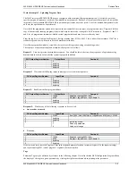
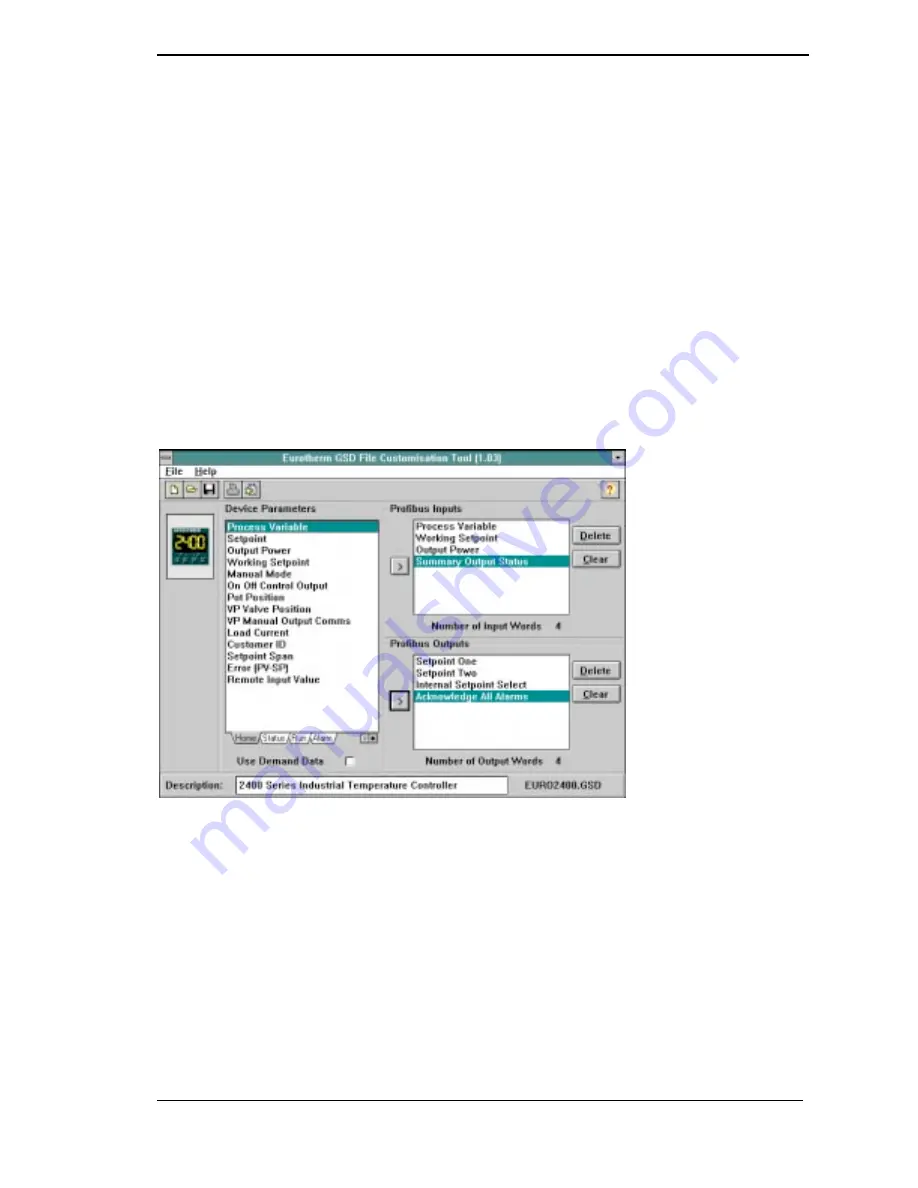
The screen layout shown below is the default screen supplied on the EURO2400.GSD file

Figure 5-1:   The Default Configurator Screen Layout.

Leave the mouse cursor over a portion of the screen to see a hint explaining how it works.  Hints can be turned off via the
Help menu once you have learned how to operate the program.

Open a GSD file for modification or editing, or create a new file for the currently selected controller type, using the ‘file’
menu.  Note, however, that only files for the Eurotherm products, which include 2400

f and T630,

 may be edited using this

program.
Selected input or output parameters may be printed using the ‘print’ command in the ‘file’ menu.
Standard Windows facilities for Save and Save As are provided, allowing GSD files to be written to disk.
The buttons on the task bar provide quick access to most of these functions.

The controller parameter set is represented by a box to the left of the screen.  A set of tabs allows a group of parameters to be
displayed, corresponding to lists in the controller user interface.  A separate list for 2400

f

 series status words is also provided

for the controller type.

Summary of Contents for 2404f

Page 1: ... Specifications 3 1 3 2 Chapter 4 CONTROLLER SET UP NETWORK CONFIGURATION Floating Point Data Formats Diagnostic Information 4 1 4 2 4 3 Chapter 5 THE WINDOWS CONFIGURATOR Installing GSD Files 5 1 5 1 Chapter 6 TROUBLESHOOTING 6 1 Chapter 7 DEMAND DATA 7 1 Chapter 8 TAG ADDRESSES 8 1 Appendix A GLOSSARY OF TERMS A 1 Appendix B EUROTHERM OFFICE ADDRESSES B 1 This product is covered by one or more o...

Page 2: ...col which is designed especially for communication between automatic control systems and distributed I O at the device level It is most often used to allow a central Programmable Logic Controller or PC based control system to use external slave devices for I O or specialised functions The principal advantage is that these devices may be distributed around a machine thereby saving on the cost of po...

Page 3: ...rent application areas as follows PROFIBUS PA is designed especially for process automation It permits sensors and actuators to be connected on one common bus line even in intrinsically safe areas PROFIBUS PA permits data communication and power over the bus using intrinsically safe 2 wire technology according to the international standard IEC 1158 2 but may also be used on the standard RS485 cabl...

Page 4: ...t registers or a single function block so that the controlling ladder logic or program interfaces with the device as if it were an internally fitted module It is NOT necessary therefore for the programmer to know anything about the physical network The process of network configuration is usually performed using a PC based program which allows the devices on the network to be defined and device par...

Page 5: ...ned by what is known as a GSD file See Chapter 5 for more details For simple devices such as digital or analogue I O blocks this is fixed However since more complex devices often have a much wider choice of possible values to send it is usually possible to edit the GSD file to change the mapping of device parameters onto Profibus inputs or outputs This is the case with most Eurotherm implementatio...

Page 6: ...to ensure that differences in local earth potential do not allow circulating currents to flow as these can not only induce large common mode signals in the data lines but can also produce potentially dangerous heating in the cable Where doubt exists it is recommended that the shield be earthed at only one section of the network Do not connect the shield to DGND SHIELD Station 1 HA HB HC HD HE HF S...

Page 7: ...nce 30 pF per Metre typ 60 pF per Metre Core diameter max 0 34 mm corresponds to AWG 22 max 0 22 mm corresponds to AWG 24 Cable type twisted pair cable 1x2 or 2x2 or 1x4 lines twisted pair cable 1x2 or 2x2 or 1x4 lines Resistance 110 Ohm per km Shielding Copper shielding braid or shielding braid and shielding foil Copper shielding braid or shielding braid and shielding foil Belden B3079A meets cab...

Page 8: ...tions if required A Modbus module fitted to any other 2000 series instrument cannot be configured to PROFIBUS DP A PDSIO master or slave module can only be fitted in module slot J PROFIBUS DP may be used with either mains powered and 24V AC DC controllers and in all respects other than those described above they are standard units and may be used in exactly the same way as other 2400 series contro...

Page 9: ...2 5 8 Note Selecting 0 4 9 or O6 will allow direct entry to these levels at this point Press to display Identity of module This should be a read only parameter displaying 1st press Press to display Comms Resolution Press or to select 9 Full or N 6 Integer 9 is the recommended setting 2nd press Press to display Function Press or to set 9 05 D This selects PROFIBUS DP protocol 3rd press If the passw...

Page 10: ...OSTICS It is possible to edit the above files or create new files using the Windows configurator The Master network configuration software uses the GSD files to produce a further file which is downloaded into your master PLC or PC supervisory package Once the configuration file has been downloaded you can set the network running If all is well the REM beacon on the controller will start to flash i...

Page 11: ...Active 0 Auto Tune disabled 1 Auto Tune active 9 Ramp Program Complete 0 Running Reset 1 Complete 10 PV out of range 0 PV within table range 1 PV out of table range 11 DC control module fault 0 Good 1 BAD 12 Programmer Segment Synchronise 0 Waiting 1 Running 13 Remote input sensor break 0 Good 1 Bad 14 IP1 Fault 15 Reserved Table 4 2 Summary Output Status Word A new diagnostics event will occur wh...

Page 12: ...ther directory Set up will add program icons to the program folder but you may type a new folder name or select one from the existing folders list Set up will then launch the program The screen layout shown below is the default screen supplied on the EURO2400 GSD file Figure 5 1 The Default Configurator Screen Layout Leave the mouse cursor over a portion of the screen to see a hint explaining how ...

Page 13: ...filename you wish You may then import it into your PROFIBUS DP network configuration tool and use it in an application program It is possible to save several different GSD files for the same basic instrument thereby setting up a library for different applications Example GSD file to allow gain scheduling using a PID settings stored in a PLC Input Data Process Variable Output Data Proportional Band...

Page 14: ...n to screening The I O data length may be too long Some PROFIBUS DP Master implementations can accept no more than 32 input and 32 output words per slave device Verify by reference to documentation of the Master Verify that the maximum line length for the baud rate in use is not exceeded see cable specifications Note that the 2404 8f is restricted to use at a maximum rate of 1 5 Mbaud Ensure that ...

Page 15: ...er using what are known as Tags which identify the parameters Each parameter has a unique 16 bit tag a full list of which is given in the next chapter When Demand Data is used the first four 16 bit registers of the PROFIBUS DP Output data are reserved to encode a request message using the protocol The control program is responsible for writing values into the first four registers to make requests ...

Page 16: ...first four registers to make requests 1 Command Code and Parameter Tag 2 Extended Parameter Tag 3 Reserved 4 Value or State to be written The registers that follow are used for the fixed output data defined by the GSD file 5 Value or State 6 Value or State 7 Value or State etc Value or State PLC Input Register Number Input Data The first four registers are reserved for responses to demand data 1 C...

Page 17: ...alue to write 3000 Extended Read Request Must be Zero Tag to Read 4000 Extended Write Request Must be Zero Tag to Write Value to Write Valid responses to a given command are as follows Command Field in request output register Command Field in response input register Meaning Returned Value input register 4 0000 0000 Acknowledge No Command 1000 1000 Tag Read Successfully Value Read 1000 7000 Tag Rea...

Page 18: ...r 8 Response 2 Wait for one of the following responses to be received a An error has occurred Code 7 PLC Input Register Number Input Data Comment 1 28942 Error 7000 Hex 28672 dec tag address 270 dec 28942 2 Anything 3 Anything 4 1 or 2 or 3 Invalid tag number Read only parameter Value out of range b No error PLC Input Register Number Input Data Comment 1 4366 Successful write code 1000 Hex 4096dec...

Page 19: ...emand data requests You should do this at the start of any sequence of operations using demand data in order to ensure that the system is properly initialised PLC Output Register Number Output Data Comment 1 0 2 Anything 3 Anything 4 Anything Response 1 Wait until the following response message is received in the input data PLC Input Register Number Input Data Comment 1 0 2 Anything 3 Anything 4 A...

Page 20: ...te 0 Safe 1 Alarm 4 Manual Mode 0 Auto 1 Manual 5 Sensor Break 0 Good PV 1 Sensor Broken 6 Loop Break 0 Good closed loop 1 Open Loop 7 Heater Fail 0 No Fault 1 Load fault detected 8 Tune Active 0 Auto Tune disabled 1 Auto Tune active 9 Ramp Program Complete 0 Running Reset 1 Complete 10 PV out of range 0 PV within table range 1 PV out of table range 11 DC control module fault 0 Good 1 BAD 12 Progr...

Page 21: ...f 1 On 11 3B module telemetry 0 Off 1 On 12 3C module telemetry 0 Off 1 On 13 AA relay telemetry 0 Off 1 On 14 Reserved 15 Reserved Digital Input Status Word 87 BIT DESCRIPTION 0 H Interface module 0 Off 1 On 1 J Interface module 0 Off 1 On 2 1A module 0 Off 1 On 3 LB logic input 0 Off 1 On 4 LA logic input 0 Off 1 On 5 1B module telemetry 0 Off 1 On 6 1C module 0 Off 1 On 7 2A module 0 Off 1 On 8...

Page 22: ... 466 96D 96D Logic 4 output current program 467 96D 96D Logic 5 output current program 468 96D 96D Logic 6 output current program 469 96D 96D Logic 7 output current program 470 96D 96D Logic 8 output current program 471 A A Segment synchronisation 0 No 1 Yes 488 D D Flash active segment in lower display 284 Advance Segment Flag 149 Skip Segment Flag 154 Program Logic Status 162 Controller Alarm Ta...

Page 23: ... D 5 Bounded sensor break strategy 128 D 1 D 1 VP Bounded sensor break 62 Controller Setpoint Tab Tag Display Parameter Description Address Select setpoint 0 SP1 1 SP2 15 2 SP 3 3 SP 4 4 SP 5 5 SP 6 6 SP 7 7 SP 8 8 SP 9 9 SP 10 10 SP 11 11 SP 12 12 SP13 13 SP14 14 SP15 15 SP16 B5 B5 Local or remote setpoint select 0 Local 1 Remote 276 1 1 Setpoint 1 24 1 1 Setpoint 2 25 1 1 Setpoint 3 164 1 1 Setp...

Page 24: ...djust input 1 146 User calibration adjust input 2 148 D D Input 1 calibration offset 141 D D Input 2 calibration offset 142 D D Input 1 measured value 202 D D Input 2 measured value 208 D D Input 1 cold junction temp reading 215 D D Input 2 cold junction temp reading 216 OD OD Input 1 linearised value 289 OD OD Input 2 linearised value 290 0 D 0 D Currently selected setpoint 291 Controller Output ...

Page 25: ... of output 209 0 0 0 0 Proportional component of output 214 N 0 N 0 Integral component of output 55 0 0 Derivative component of output 116 0 0 VP motor calibration state 0 Start 1 Waiting 2 Open valve 3 BLUp InDn 4 Ttup 5 Overshoot 6 InUp BLDn 7 TT down 8 Open 9 Low lim 10 Stopping 11 Raise 12 Inert up 13 Lower 14 Low lim 15 Stopping 16 Lower 17 InDn BL 99 Abort 210 Controller I O Tab Tag Display ...

Page 26: ...tput level 556 BCD input function 0 None 1 Select program number 2 Select SP number 522 Gain schedule enable 0 No disabled 1 Yes enabled 567 Controller Display Custom Linearisation Tab Tag Address Parameter Description O O Custom linearisation input 1 601 D D Display value corresponding to input 1 621 O O Custom linearisation input 2 602 D D Display value corresponding to input 2 622 O O Custom li...

Page 27: ...king 0 Off 1 Track 526 D65 D65 Manual tracking 0 Off 1 Track 527 05D65 05D65 Programmer tracking 0 Off 1 Track 528 5 0D 5 0D Setpoint rate limit units 0 Sec 1 Min 2 Hour 531 5 6 5 6 Remote setpoint configuration 0 None 1 Remote setpoint 2 Remote setpoint local trim 4 Remote trim local setpoint 535 Controller Display Alarm Configuration Tag Address Parameter Description Alarm 1 type 0 Off 1 Full sc...

Page 28: ...meter Description O O Identity 4 Logic 12352 9 9 Input functions 192 None 193 Manual mode select 194 Remote setpoint select 195 Setpoint 2 select 196 PID set 2 select 197 Integral hold 198 One shot self tune enable 199 Adaptive tune enable 200 Acknowledge alarms 201 Select full access level 202 Keylock 203 Up button 204 Down button 205 Scroll button 206 Page button 207 Run 208 Hold 209 Run Hold 21...

Page 29: ... 9 Module function For O 5 or 5 12675 0 None 1 Digital output 2 Heating output 3 Cooling output 4 Open motorised valve 10 PDSIO mode 1 heating 11 PDSIO mode 2 heating For O D5 or D 0 16 None 17 Heating output 18 Cooling output 19 Retransmission of PV 20 Retransmission of SP 21 Retransmission of error 22 Retransmission of OP power For O DO Use the enumerators in LA Config list D D PID or Retran val...

Page 30: ...2 Feedforward input 163 Remote OP power high 164 Remote OP power low 165 Valve position 12739 D D PID or Retran low value 12751 D D Potentiometer input low scalar 12763 D D PID or Retran high value 12750 D D Potentiometer input high scalar 12762 9 O6 9 O6 Units 1 Volts 2 mA 12748 96D 96D Minimum electrical output 12753 96D 96D Maximum electrical output 12752 Sense of output 0 Normal 1 Inverted 127...

Page 31: ... 12818 D D Input module 3A low value 12829 D D Input module 3A high value 12828 D D Module 3A low value 12815 D D Potentiometer input 3A low scalar 12827 D D Module 3A high value 12814 D D Potentiometer input 3A high scalar 12826 9 O6 9 O6 Units 3A 1 Volts 2 mA 12812 96D 96D Minimum electrical output 12817 96D 96D Maximum electrical output 12816 Sense of output 0 Normal 1 Inverted 12809 Summary ou...

Page 32: ... Program 4 8736 2220 The parameters used to describe a program are organised into 17 blocks each of 8 words in length starting at the base address for the program There is one block for general program data such as the units to be used for ramp and dwell times and 16 further blocks for the segment data itself To obtain the tag address of the data block for a given program add the block offset give...

Page 33: ...ATE RAMP TIME TO TARGET CALL END 0 Segment Type Segment Type Segment Type Segment Type Segment Type Segment Type 1 Target Setpoint Target Setpoint Target Setpoint 2 Duration Rate Duration 3 Program Number End Type 4 Logic O P s Logic O P s Logic O P s Logic O P s Call Cycles Logic O P s 5 6 7 Example Address calculations Program 1 Segment 4 Segment Type 8328 32 0 8360 20A8 Hex Program 2 Holdback V...

Page 34: ... EQOOWPKECVKQPU U UVGOU UWEJ CU 45 45 CPF 5 KGNFDWU GUUCIG 5RGEKHKECVKQP 5 FGHKPGU VJG CRRNKECVKQPU UGTXKEGU HQT 241 75 5 5 GXKEG CVC CUG KNG NGEVTQPKE FGXKEG FCVC UJGGV 5 QUV UKIPKHKECPV D VG 5 GCUV UKIPKHKECPV D VG 0QP U PEJTQPQWU FCVC EJCPPGN KP YJKEJ PQ VKOKPI KPHQTOCVKQP KU VTCPUHGTTGF DGVYGGP EQOOWPKECVKPI FGXKEGU 2 2TQEGUU WVQOCVKQP 2 KU VJG 241 75 UQNWVKQP HQT VJG RTQEGUU CWVQOCVKQP KPFWUV...

Page 35: ... Faraday Close Durrington Worthing West Sussex BN13 3PL Telephone Sales 01903 695888 Technical 01903 695777 Service 01903 695444 Fax 01903 695666 email http www eurotherm co uk USA SALES OFFICE Eurotherm Controls Inc 11485 Sunset Hills Rd Reston Virginia 20190 5286 USA website http www eurotherm com controls htm Telephone 703 471 4870 Fax 703 787 3436 email info controls eurotherm com ...

Reviews: