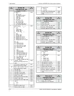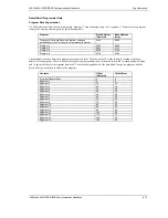
Tag Addresses 2408
f & 2404f PROFIBUS Communications Handbook
8-6 2408
f & 2404f PROFIBUS Communications Handbook
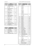
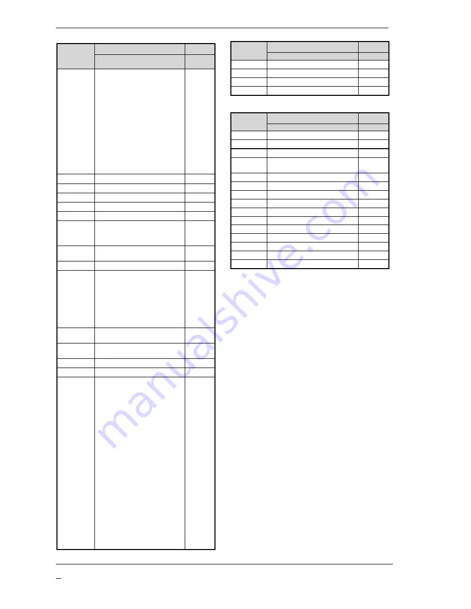
Controller
Information Tab
Tag
Display
Parameter Description
Addres
s
O0
O0
Configuration of lower readout
display
0: Standard
1: Load current
2: Output power
3: Status
4: Program time
5: None
6: Valve position
7: Process value 2
8: Ratio setpoint
9: Selected program number
10: Remote setpoint
106
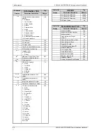
)/!D)
)/!D)
PV minimum
134
)/!D#
)/!D#
PV maximum
133
)/!D
)/!D
PV mean value
135
)/!D6
)/!D6
Time PV above threshold level
139
)/!D:
)/!D:
PV threshold for timer log
138
5D)
5D)
Logging reset
0: Not reset
1: Reset
140
,6
,6
Maximum Control Task Time
(Processor utilisation factor)
201
=D0
=D0
Working output
4
5
5
PDSIO SSR status
0: Good
1: Load fail
2: Open
3: Heater fail
4: SSR fail
5: Sn fail
79
D0
D0
Feedforward component of
output
209
0 0
0 0
Proportional component of
output
214
N 0
N 0
Integral component of output
55
0
0
Derivative component of output
116
:0
:0
VP motor calibration state
0: Start
1: Waiting
2: Open valve
3: BLUp/InDn
4: Ttup
5: Overshoot
6: InUp/BLDn
7: TT down
8: Open
9: Low lim
10: Stopping
11: Raise
12: Inert up
13: Lower
14: Low lim
15: Stopping
16: Lower
17: InDn/BL
99: Abort
210
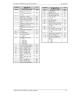
Controller
I/O Tab
Tag
Display
Parameter Description
Address
DC Output 1A Telemetry
12694
DC Output 2A Telemetry
12758
DC Output 3A Telemetry
12822
BCD Input Value
96
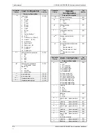
Controller
Miscellaneous Tab
Tag
Display
Parameter Description
Address
Instrument Mode
199
Instrument Version Number
107
Instrument Ident
122
Slave Instrument Target
Setpoint
92
Slave Instrument Ramp Rate
93
Slave Instrument Sync
94
Remote SRL Hold
95
CNOMO Manufacturers ID
121
Remote Parameter
151
Error Logged Flag
73
Ramp Rate Disable
78
Maximum Input Value
548
Minimum Input Value
549
Holdback Disable
278
All User Interface Keys Disable
279


