background image

2 Flow of operations


Work Procedures  2-3


2.  Flow of operations 

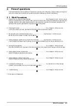
The flowchart below shows the flow of operations necessary for configuring a network base card system. 

Use it as a reference to perform the required operations without any excess or deficiency. 


2.1.  Work Procedures 

1

  Determining the Network Specifications   .........................................   See Chapters 3 and 4 of this manual. 

With an understanding of the network base card and communication module specifications, determine the 

interface related to the system signals using the communication module. (For example, assignment of 

dedicated I/O signals, specification o

f general-

purpose I/O signals).


2


Checking Products 

 ...........................................................................   See Chapter 

5

 of this manual. 

Check the product you have purchased and prepare other products as needed.   


3  Mounting Module onto Network Base Card   .............................   See Section 

6.1

 of this manual.   

Mount the communication module onto 

2F

-DQ

535.


4  Setting Hardware and Mounting onto Robot Controller   ...........   See Section 

6.2

 of this manual.   

The 

2F

-DQ

535 hardware 

has no settings, so mount the 

2F

-DQ

535 onto the robot controller

 as it is. 


5

  Wiring and Connections   ...................................................................   See Chapter 

7

 of this manual.   

Wire the 

2F

-DQ

535 card mounted on the robot controller to the master station using an Ethernet cable.


6

  Setting Master St

ation Parameters 

 ..................................................   See Chapter 8 of this manual.   

Set the IP address with the master station.


7


Setting Robot Controller Parameters

   ...............................................   See Chapter 8 of this manual.   

Set the IP address on the robot controller side.


Creating Robot Programs

   ................................................................   See Section 8.3 of this manual.   

Create a robot program, and run it with automatic operation. 


9  Troubleshooting   ...............................................................................   See Chapter 9 of this manual. 


10

 Completion of Operations   

Summary of Contents for 2F-DQ535

Page 1: ...CR800 D series controller Network Base Card Instruction Manual 2F DQ535 Mitsubishi Electric Industrial Robot BFP A3526 A...

Page 2: ......

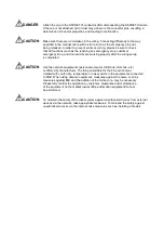
Page 3: ...g work This also applies to maintenance work with the power source turned ON Setting of emergency stop switch CAUTION During teaching work place a sign indicating that teaching work is in progress on...

Page 4: ...not apply excessive force on the connector or excessively bend the cable Failure to observe this could lead to contact defects or wire breakage CAUTION Make sure that the workpiece weight including t...

Page 5: ...ogram parameter writing could break the internal information of the robot controller DANGER Do not connect the Handy GOT when using the GOT direct connection function of this product Failure to observ...

Page 6: ...wiring setup is completed CAUTION Use the network equipments personal computer USB hub LAN hub etc confirmed by manufacturer The thing unsuitable for the FA environment related with conformity temper...

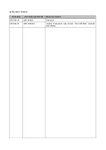
Page 7: ...Revision History Print date Instruction manual No Revision content 2017 05 31 BFP A3526 First print 2018 02 01 BFP A3526 A Safety Precautions was revised The CR800 Q controller was added...

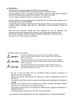
Page 8: ...ases where there is a risk of operator fatality or serious injury if handling is mistaken Always observe these precautions to safely use the robot WARNING Precaution indicating cases where the operato...

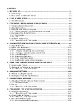
Page 9: ...ster number map CC Link IE Field 4 13 4 3 3 Flow of I O signal 4 14 4 3 4 Deducated Input Output 4 14 4 3 5 Output signal Reset pattern 4 15 4 3 6 Specifications related to Robot language 4 16 5 ITEMS...

Page 10: ...ing general purpose input output 8 37 8 3 4 Sample program for input output confirmation 8 38 9 TROUBLESHOOTING 9 39 9 1 List of Errors 9 39 10 APPENDIX 10 41 10 1 Displaying the Option Card Informati...

Page 11: ...troller distributed control I O control safety control and motion control It enables flexible wiring with the topology such as star line or ring depending on the production line or the layout of equip...

Page 12: ...rk Base Card 2F DQ535 Chapter 3 describes the features of the DQ535 card and for mounting the module 4 2F DQ535 Card and Ethernet IP Module Specifications Chapter 4 describes the specifications of the...

Page 13: ...and prepare other products as needed 3 Mounting Module onto Network Base Card See Section 6 1 of this manual Mount the communication module onto 2F DQ535 4 Setting Hardware and Mounting onto Robot Con...

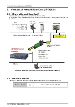
Page 14: ...d Figure 3 1 Example of configuring CC Link IE Field with network base card 3 2 Mountable Modules The modules which can be mounted on the network base card 2F DQ535 are shown below Mountable module CC...

Page 15: ...or input registers 144 bytes in total 128 bits 16 bytes for output signals 64 words 128 bytes for output registers 144 bytes in total Example 2 2048 bits 256 bytes for input signals 0 words 0 bytes fo...

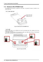
Page 16: ...ure 3 2 Overall view of 2F DQ535 card 3 4 2 LED There are three LEDs on the 2F DQ535 card and the operating state of the interface card can be confirmed by each on off The shape and specifications of...

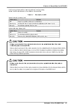
Page 17: ...r EXCEPTION state FATAL error etc It takes some time for the communication line to be established after the cable is connected It takes about one minute for the communication line to be established fo...

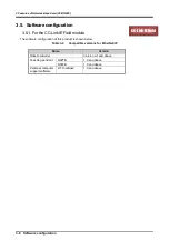
Page 18: ...Link IE Field module The software configuration of this product is shown below Table 3 2 Compatible versions for EtherNet IP Name Version Robot controller Version A1 and above Teaching pendant R32TB...

Page 19: ...um Twisted pair cable 1000BASE T standard compliant Ethernet cable Category 5e or higher double shielded STP straight cable Connector specifications Shielded RJ45 connector compatible with ANSI TIA EI...

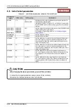
Page 20: ...a size in bytes for the input signals bit devices As 8 bits equal to 1 byte the maximum data size for the input signals is 2048 bits which equal to 256 bytes Set a value in multiples of two CFNOTB 16...

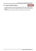
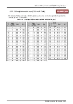
Page 21: ...dled in the robot controller is 2048 bits starting at address 6000 through 8047 for both input and output regardless of the CC Link IE Field node or station number The maximum data size of I O registe...

Page 22: ...55 118 944 6000 to 6943 204 1632 6000 to 7631 34 272 6000 to 6271 120 960 6000 to 6959 206 1648 6000 to 7647 36 288 6000 to 6287 122 976 6000 to 6975 208 1664 6000 to 7663 38 304 6000 to 6303 124 992...

Page 23: ...392 196 6000 to 6195 48 24 6000 to 6023 224 112 6000 to 6111 400 200 6000 to 6199 56 28 6000 to 6027 232 116 6000 to 6115 408 204 6000 to 6203 64 32 6000 to 6031 240 120 6000 to 6119 416 208 6000 to 6...

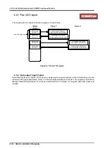
Page 24: ...area for robot 1 Output area for robot 2 Input area for robot 2 Input signal bit device Input register word device Output signal bit device Output register word device Figure 4 1 Flow of I O signal 4...

Page 25: ...2 7343 ORST6320 6320 6351 ORST7344 7344 7375 ORST6352 6352 6383 ORST7376 7376 7407 ORST6384 6384 6415 ORST7408 7408 7439 ORST6416 6416 6447 ORST7440 7440 7471 ORST6448 6448 6479 ORST7472 7472 7503 ORS...

Page 26: ...data to designated output signal Write M_Inw Integer 1 Reads 16 bits of data from designated input signal Read M_Outw Integer 1 Writes 16 bits of data to designated output signal Write M_In32 Integer...

Page 27: ...n manual and make arbitrary assignments of the I O signals Figure 4 2 Example of using interlock An example of the robot program corresponding to Figure 4 2 flow chart is given below Refer to the inst...

Page 28: ...owing items as standard Please verify the items Table 5 1 List of the standard items in the product 2F DQ535 No Name Model Quantity 1 Instruction Manual CD ROM BFP A3544 1 2 Network base card 2F DQ535...

Page 29: ...tion compatible with CC Link IE Field CC Link IE Field module An Anybus CompactCom module by HMS Anybus CC CC Link IE Field module AB6709 Ethernet cable This cable must conform to the specification of...

Page 30: ...e card 2F DQ535 CC Link IE Field module and module fixing parts Remove the card handle fixing screws from the network base card 2F DQ535 and separate the card from the card handle 2 Insert the protrus...

Page 31: ...de with the slits on the module and mount the module as if sandwiching it from the left right and top Adjust the position of the module so that the screw holes on the top fixing parts and bottom fixin...

Page 32: ...e 7 Fasten the card and card handle with screws This completes the module mounting process Tighten the screws with a cross point driver 6 2 Setting the 2F DQ535 Card Hardware The 2F DQ535 card does no...

Page 33: ...over of the option slots 2 in the robot controller front and mount the 2F DQ535 card there Please use the handle of the interface card at mounting of the interface card Connector Handle Removal lever...

Page 34: ...2F DQ535 card on which the CC Link IE Field module is mounted 2 Connect the other connector to the hub 3 Connect the Ethernet straight cable connector to the P1 for Ethernet on QJ71GF11 T2 For the sta...

Page 35: ...using the 2F DQ535 card Table 7 1 Checking connections No Check item Check 1 Is the 2F DQ535 card securely mounted into the controller slot 2 Are the Ethernet cables between the 2F DQ535 card and pre...

Page 36: ...operation Table 8 1 Example of equipment on the master station side Master station equipment Mitsubishi Electric MELSEC iQ Q03UDVCPU QJ71GF11 T2 Software used GX Works2 engineering software CC Link I...

Page 37: ...the Parameters 8 27 8 1 Setting the Parameters 8 1 1 For the CC Link IE Field module 1 Start GX Works2 and create a new PLC project 2 Set the CPU module model Select the model 3 Open the parameter se...

Page 38: ...arameters module 1 Network Type CC IE Field Master Station Start I O No 0000 Network No 1 Total Stations 1 5 Set the network configuration Station No 1z Station Type Intelligent Device Station RX RY S...

Page 39: ...port the word devices D200 to D263 of PLC into the input registers 6000 to 6063 of the robot Specifically set the refresh parameters on the PLC side as follows Transfer 1 Link Side Dev Name RX Points...

Page 40: ...0 to M127 to the bit devices M2000 to M2127 Copy the 64 point word devices D0 to D63 to the word devices D200 to D263 An output of the robot is looped back in the PLC to be an input of the robot Robot...

Page 41: ...by using RT ToolBox3 The parameters of the robot have been set with the factory setting When they are not changed from the initial values the values do not need to be checked CFNNWNO 1 CC Link IE Fie...

Page 42: ...Starting Operation 8 32 Setting the Parameters The parameter settings and the network configuration settings station No and number of points of RX RY and RWr RWw must be consistent with those in the P...

Page 43: ...he I O Signals 8 33 8 2 Checking the I O Signals 8 2 1 For the CC Link IE Field module Check the exchange of I O signals using RT ToolBox3 and the GX Works2 monitor screen 1 Start the General Purpose...

Page 44: ...w and specify the beginning M0 M2000 D0 D200 of the device name to be monitored Multiple monitors can be started at the same time and pressing the F3 key starts monitoring 3 Click the Forced Output bu...

Page 45: ...8 Procedures for Starting Operation Checking the I O Signals 8 35 4 Confirm that the output from the robot is looped back in the PLC side and stored in the input of the robot...

Page 46: ...ART Program start 6001 Program starting 6001 STOP2 Stop 6002 Stopping 6002 SLOTINIT Program reset 6003 Program selection enabled 6003 SRVON Servo power ON 6004 Servo ON 6004 SRVOFF Servo power OFF 600...

Page 47: ...Select End LOAD Return UNLOAD Return GOHOME Return Input No 6008 and output No 6009 are used as interlocks Refer to 4 5 1 Robot system status variables for 2D DQ535 card for details on the interlock W...

Page 48: ...s Copy all input bits to the output bits Program example 1 Loop the input signal to the robot back to the output signal For bit checking For M1 6000 To 8047 M_Out M1 M_In M1 Copy with bit variable Nex...

Page 49: ...ed module mounted error Cause An unsupported HMS module board is mounted in the network base card Measures Replace the module H 6110 Error message Multiple network base cards are mounted Cause Only on...

Page 50: ...is started while an error is occurring n 1 Ethernet cable is disconnected n 2 IP address is not established Measures Check the cable and parameters H 6140 Error message Parameter error parameter name...

Page 51: ...ick Online in the work space tree and click Slot n n 1 to 3 Network Base under Board The 2F DQ535 card information will be read into the properties window The option card information in the properties...

Page 52: ...k base card LED_1 Green Module Status LED status LED_2 Green Network Status LED status Input RX 16 6000 6127 RWr 16 6000 6063 Number of received bytes signal number Up to 256 bytes in total of the inp...

Page 53: ...connected but a communication error occurring 4 In normal communication indicates usable and indicates not usable A pseudo input is not possible while an error is occurring Usage method 1 Start RT To...

Page 54: ......

Page 55: ......

Page 56: ...Feb 2018 MEE Printed in Japan on recycled paper Specifications are subject to change without notice...

Reviews: