1
ENGINE Cylinder Head and Valves
0.5 mm
in.)
1 mm
in.)
Oversize I.D.
1
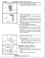
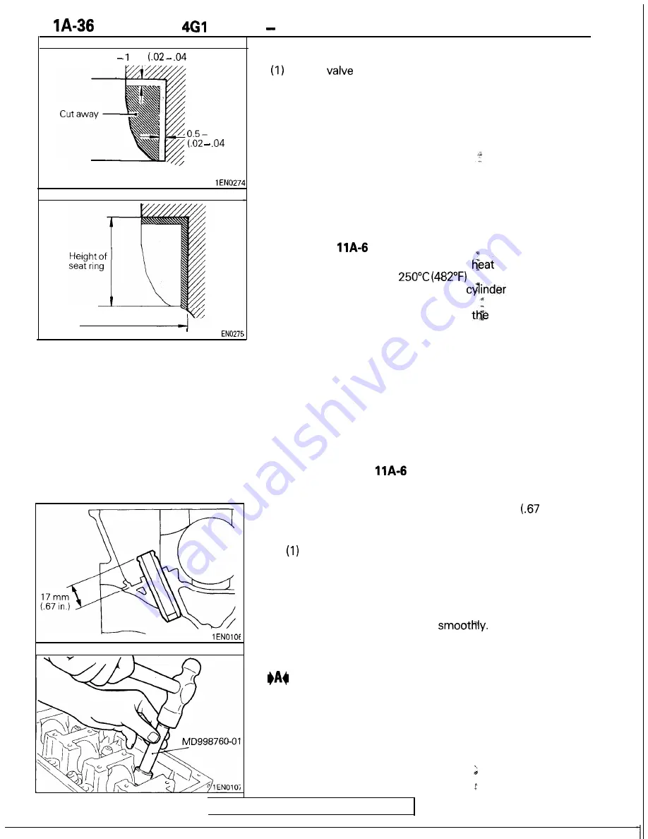
VALVE SEAT REPLACEMENT PROCEDURE
Cut the
seat to be replaced from the inside to thin the
wall thickness. Then, remove the valve seat.
(2) Rebore the valve seat hole in cylinder head to a selected
oversize valve seat diameter.
Seat
ring
hole diameter: See “Service Specifications”
in page
(3) Before fitting the valve seat, either
the cylinder head
up to approximately
or cool the valve seat
using cooling spray, to prevent the
head bore from
galling.
(4) Using valve seat cutter, correct
valve seat to the
specified width and angle. See “VALVE SEAT RECON-
DITIONING PROCEDURE.”
VALVE GUIDE REPLACEMENT PROCEDURE
(1) Push out the valve guide toward the combustion chamber
side using a press.
(2) Rebore the valve guide hole in the cylinder head to the size
corresponding to the oversize valve guide to be installed.
Caution
Do not install a valve guide of the same size again.
Valve guide hole diameter: See “Service Specifica-
tions” in page
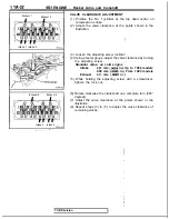
(3) Install the valve guide until it projects 17 mm
in.) from
the cylinder head as illustrated.
NOTE
The valve guide must be installed from the upper side of
the cylinder head.
(2) Note that the intake and exhaust valve guides differ in
length: 44 mm (1.732 in.) on intake side, 49.5 mm
(1.949 in.) on exhaust side.
(3) After installation of the valve guide, install a new valve
and check that it slides
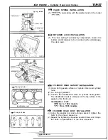
REASSEMBLY SERVICE POINTS
VALVE STEM SEAL INSTALLATION
(1) Install the valve spring seat.
(2) The special tool must be used to install the valve stem seal.
Improper installation could result in oil leaking past the valve
guide.
Caution
Do not reuse removed valve stem seal.
TSB Revision
Summary of Contents for 4G1 series
Page 2: ......
Page 11: ...4Gl ENGINE General Information TSB Revision 1 ...
Page 12: ...VA 4 4Gl ENGINE General Information UBRICATION SYSTEM P 0 Z t7 ii ii I OTJ 09 1 TSB Revision ...
Page 21: ...4Gl ENGINE Special Tools Valve stem seal compressor Flywheel stopper 1 TSB Revision ...
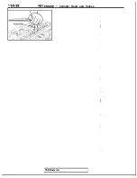
Page 46: ...1 IA 38 461 ENGINE Cvlinder Head and Valves TSB Revision ...
Page 62: ...N O T E S ...
Page 65: ...4G3 ENGINE General Information pqJp3 I 3EN0087 TSB Revision ...
Page 66: ...IIB 4 4G3 ENGINE General Information JBRICATION SYSTEM 3LUOO20 TSB Revision ...
Page 77: ...463 ENGINE Special Tools Removal of crankshaft sprocket 1 TSB Revision ...
Page 106: ...11 B 44 4G3 ENGINE Cylinder Head and Valves 3EN018E TSB Revision ...
Page 127: ...4G6 ENGINE 1992 General Information 6EN0314 TSB Revision I ...
Page 128: ...IIC 4 466 ENGINE 1992 General Information NGlNE SECTIONAL VIEW DOHC TSB Revision ...
Page 129: ...6EN0244 TSB Revision ...
Page 225: ...4G6 ENGINE 1992 Piston and Connecting Rod 1 IC 101 TSB Revision ...
Page 232: ...NOTES ...
Page 235: ...4G9 ENGINE General Information llD 3 ru l 9EN0105 TSB Revision ...
Page 236: ...11D 4 4G9 ENGINE General Information UBRICATION SYSTEM 9EN0106 TSB Revision ...
Page 284: ...NOTES ...
Page 287: ...6G7 ENGINE General Information llE 3 TEN0324 1 Revision ...
Page 289: ...667 ENGINE General Information TSB Revision 7EN0120 I ...
Page 290: ...WE 6 6G7 ENGINE General Information SECTIONAL VIEW DOHC NON TURBO ENGINE TSB Revision 7EN0325 ...
Page 291: ......
Page 292: ...IIE 8 6G7 ENGINE General Information SECTIONAL VIEW DOHC TURBO ENGINE 1 TSB Revision 7EN0335 ...
Page 293: ...667 ENGINE General Information IIE 9 TSB Revision 7EN0334 ...
Page 409: ...4G6 ENGINE 1993 General Information TS8 Revision 6EN0630 ...
Page 411: ...466 ENGINE 1993 General Information 6EN0614 TSB Revision ...
Page 412: ...4G6 ENGINE 1993 General Information ENGINE SECTIONAL VIEW DOHC 6EN0619 TSB Revision ...
Page 413: ...4G6 ENGINE 1993 General Information I W7 6EN0620 TSB Revision ...
Page 522: ...NOTES ...

