13-58
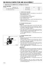
1. Inspecting No-load Minimum and Maximum Speeds
Service standards
1.1 Work before inspection
•
Before starting the inspection and adjustment, carry out the fol-
lowing preparatory steps.
•
Put the transmission in neutral.
•
Turn the steering wheel in neutral position.
•
Turn off all lamps and accessories.
•
Attach a Multi-Use Tester.
•
Warm up the engine until the engine coolant temperature is ap-
proximately 80 to 95
°
C.
(Verify from Service Data “2E: Water Temperature”)
1.2 No-load minimum speed
[Inspection]
•
With the accelerator pedal released, measure the engine speed.
•
If the measurement deviates from the standard value, check for
an installed condition of the accelerator control cable and accel-
erator link. (See “ENGINE CONTROL”.)
•
If the cable and link are found to be normal, check for the accel-
erator pedal switch
*a
, accelerator pedal position sensor
*a
, sup-
ply pump
*b
and engine electronic control unit
*b
.
(*a: See “ENGINE CONTROL”, *b: Contact Bosch Service Sta-
tion for repair.)
1.3 No-load maximum speed
[Inspection]
•
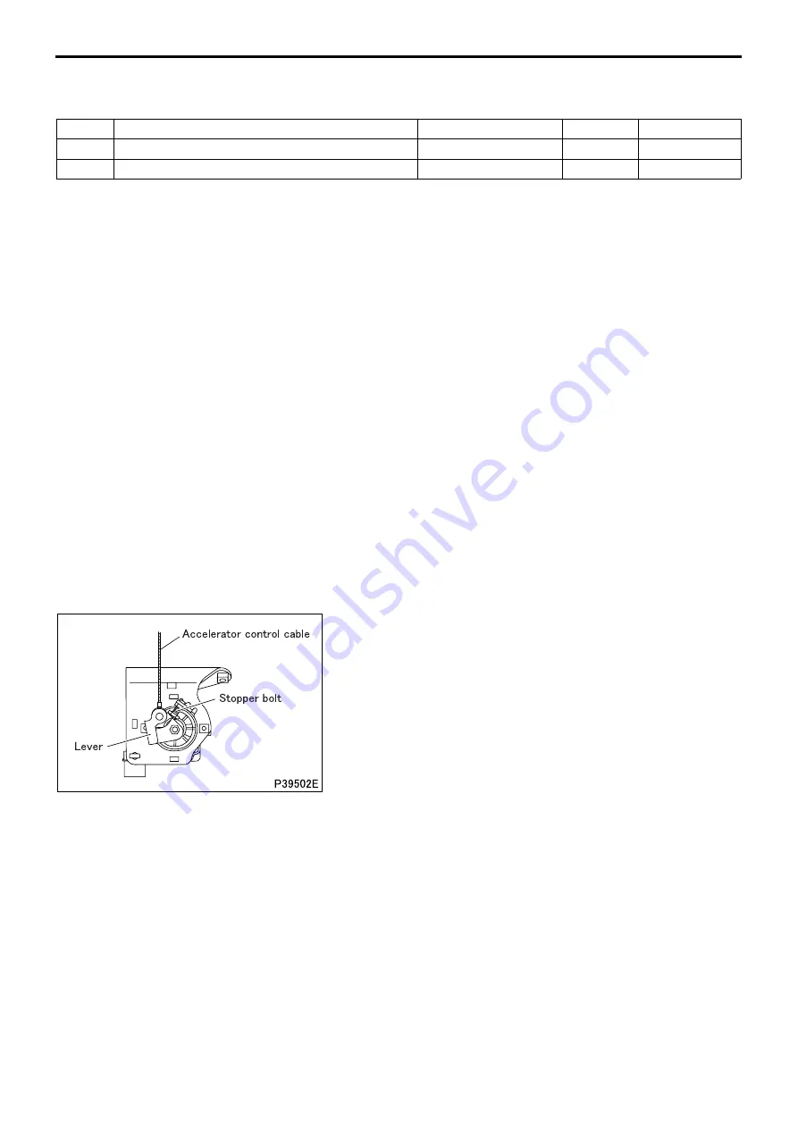
Measure the engine speed with the accelerator pedal pressed
against the stopper bolt.
•
If the measurement deviates from the standard value, check for
an installed condition of the accelerator control cable and accel-
erator link. (See “ENGINE CONTROL”.)
•
If the cable and link are found to be normal, check for the accel-
erator pedal switch
*a
, accelerator pedal position sensor
*a
, sup-
ply pump
*b
and engine electronic control unit
*b
.
(*a: See “ENGINE CONTROL”, *b: Contact Bosch Service Sta-
tion for repair.)
[Adjustment]
•
If the measurement deviates from the standard value, adjust the
stopper bolt to change the accelerator pedal travel until the opti-
mum engine speed is reached with the pedal pressed.
•
If it cannot be adjusted within the standard value by using the
stopper bolt, check for an installed condition of the accelerator
control cable and accelerator link. (See “ENGINE CONTROL”.)
•
If the cable and link are found to be normal, check for the accel-
erator pedal switch
*a
, accelerator pedal position sensor
*a
, sup-
ply pump
*b
and engine electronic control unit
*b
.
(*a: See “ENGINE CONTROL”, *b: Contact Bosch Service Sta-
tion for repair.)
•
After the adjustment, make sure that the accelerator pedal
moves smoothly by firmly pressing the pedal 10 to 15 times until
it contacts the stopper bolt.
Location
Maintenance item
Standard value
Limit
Remedy
–
No-load minimum speed (idling speed)
450 to 500 rpm
–
Inspect
–
No-load maximum speed
2330 to 2370 rpm
–
Inspect
ON-VEHICLE INSPECTION AND ADJUSTMENT
Summary of Contents for 6M70
Page 29: ...M E M O 11 19 11 ...
Page 35: ...M E M O 11 25 11 ...
Page 36: ...11 26 MITSUBISHI 6M70 ROCKER COVER ROCKER AND SHAFT ...
Page 40: ...11 30 MITSUBISHI 6M70 CAMSHAFT AND ROCKER CASE ...
Page 47: ...M E M O 11 37 11 ...
Page 48: ...11 38 MITSUBISHI 6M70 CYLINDER HEAD AND VALVE MECHANISM ...
Page 63: ...M E M O 11 53 11 ...
Page 71: ...M E M O 11 61 11 ...
Page 77: ...M E M O 11 67 11 ...
Page 81: ...M E M O 11 71 11 ...
Page 98: ...11 88 MITSUBISHI 6M70 CRANKSHAFT AND CRANKCASE ...
Page 127: ...M E M O 12 21 12 ...
Page 129: ...M E M O 12 23 12 ...
Page 135: ...M E M O 13 3 13 ...
Page 138: ...13 6 1 1 Mitsubishi 6M70 Supply pump STRUCTURE AND OPERATION ...
Page 150: ...13 18 10 Electronic control unit connection diagram STRUCTURE AND OPERATION ...
Page 151: ...13 13 19 ...
Page 155: ...M E M O 13 23 13 ...
Page 185: ...M E M O 13 53 13 ...
Page 189: ...M E M O 13 57 13 ...
Page 205: ...M E M O 13 73 13 ...
Page 211: ...M E M O 13 79 13 ...
Page 215: ...M E M O 13 83 13 ...
Page 219: ...M E M O 13 87 13 ...
Page 225: ...M E M O 13 93 13 ...
Page 226: ...13 94 INSTALLED LOCATIONS OF PARTS ...
Page 227: ...13 13 95 ...
Page 228: ...13 96 INSTALLED LOCATIONS OF PARTS ...
Page 229: ...13 13 97 ...
Page 230: ...13 98 INSTALLED LOCATIONS OF PARTS ...
Page 231: ...13 13 99 ...
Page 232: ...13 100 MITSUBISHI 6M70 INSTALLED LOCATIONS OF PARTS ...
Page 233: ...13 13 101 ...
Page 234: ...13 102 ELECTRIC CIRCUIT DIAGRAM ...
Page 235: ...13 13 103 ...
Page 236: ...13 104 ELECTRIC CIRCUIT DIAGRAM ...
Page 237: ...13 13 105 ...
Page 238: ...13 106 ELECTRIC CIRCUIT DIAGRAM ...
Page 241: ...14 14 3 1 Mitsubishi 6M70 Cooling System Flow of Coolant STRUCTURE AND OPERATION ...
Page 252: ...14 14 Periphery of Engine DISCONNECTION AND CONNECTION OF HOSES AND PIPES ...
Page 271: ...M E M O 14 33 14 ...
Page 286: ...M E M O 15 13 15 ...
Page 295: ...15 22 7 Installed Locations of Parts TURBOCHARGER CONTROL SYSTEM ...
Page 296: ...15 15 23 ...
Page 297: ...15 24 TURBOCHARGER CONTROL SYSTEM ...
Page 298: ...15 15 25 ...
Page 299: ...15 26 TURBOCHARGER CONTROL SYSTEM ...
Page 300: ...15 15 27 ...
Page 301: ...15 28 TURBOCHARGER CONTROL SYSTEM ...
Page 302: ...M E M O 15 29 15 ...
Page 303: ...15 30 8 Electric Circuit Diagram TURBOCHARGER CONTROL SYSTEM ...
Page 304: ...15 15 31 ...
Page 305: ...15 32 TURBOCHARGER CONTROL SYSTEM ...
Page 306: ...M E M O 15 33 15 ...
Page 330: ...M E M O 15 57 15 ...
Page 340: ...17 6 1 3 Electronic control unit connection diagram STRUCTURE AND OPERATION ...
Page 343: ...M E M O 17 9 17 ...
Page 351: ...M E M O 17 17 17 ...
Page 352: ...17 18 8 Installed Locations of Parts EXHAUST GAS RECIRCULATION SYSTEM ...
Page 353: ...17 17 19 ...
Page 354: ...17 20 EXHAUST GAS RECIRCULATION SYSTEM ...
Page 355: ...17 17 21 ...
Page 356: ...17 22 EXHAUST GAS RECIRCULATION SYSTEM ...
Page 357: ...17 17 23 ...
Page 358: ...17 24 9 Electric Circuit Diagram EXHAUST GAS RECIRCULATION SYSTEM ...
Page 359: ...17 17 25 ...
Page 360: ...17 26 MITSUBISHI 6M70 EGR VALVE EGR MAGNETIC VALVE EGR PIPE AND EGR COOLER ...


