00-22
1. Diagnosis Codes
•
Diagnosis codes indicate the faulty sections of the vehicle.
•
A fault can be repaired by reading out the diagnosis code(s) stored in the control unit and performing the remedy
for that code(s).
•
Diagnosis codes can be displayed in the following two methods. Select either of them according to the system to
be diagnosed.
•
Using a Multi-Use Tester
•
Using flashing of a warning lamp on meter cluster
•
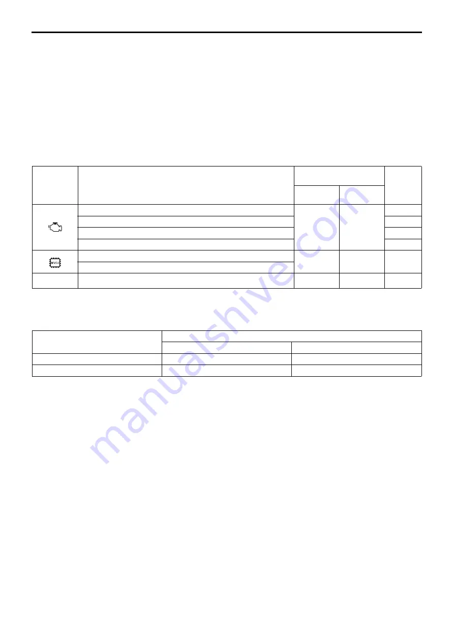
The table below indicates the systems for which diagnosis codes can be displayed and the methods usable for in-
dividual systems.
1.1 Systems and diagnosis code displaying methods
1.2 Types of diagnosis codes
•
There are two types of diagnosis code output method depending on the system: one has a distinction of present
and past codes, and the other does not have such a distinction.
(1) The system that has a distinction of present and past diagnosis codes
(1.1) Present diagnosis code
•
Fault developed in the vehicle after the starter switch is set to ON is indicated by corresponding diagnosis code.
•
The fault warning lamp is lit at the same time.
(1.2) Past diagnosis code
•
Past fault developed in the vehicle is indicated by corresponding diagnosis code stored in the memory of the elec-
tronic control unit.
•
With the vehicle restored to its normal condition or the starter switch turned from OFF to ON after inspection or re-
pair against present diagnosis codes, the present diagnosis code is stored as past diagnosis codes in the memory
of the electronic control unit.
•
When reading out the past diagnosis codes, the warning lamp does not illuminate as such codes do not indicate
the current fault.
(2) The system that does not have a distinction of present and past diagnosis codes
•
The present and past diagnosis codes are displayed together without distinction.
Warning
lamp
System
Diagnosis codes
displaying methods
Reference
Gr
Multi-Use
Tester
Flashing of
warning lamp
Common rail
O
O
13
Turbocharger
15
Exhaust gas recirculation
17
Starter continuous energizing preventing function
54
Vehicle speed limiting (SLD)
O
O
54
Auto cruise
–
Full auto air conditioner
O
O
55
System
Diagnosis code
With distinction of present and past
Without distinction
Except below
O
–
Full auto air conditioner
–
O
DIAGNOSIS CODES
Summary of Contents for 6M70
Page 29: ...M E M O 11 19 11 ...
Page 35: ...M E M O 11 25 11 ...
Page 36: ...11 26 MITSUBISHI 6M70 ROCKER COVER ROCKER AND SHAFT ...
Page 40: ...11 30 MITSUBISHI 6M70 CAMSHAFT AND ROCKER CASE ...
Page 47: ...M E M O 11 37 11 ...
Page 48: ...11 38 MITSUBISHI 6M70 CYLINDER HEAD AND VALVE MECHANISM ...
Page 63: ...M E M O 11 53 11 ...
Page 71: ...M E M O 11 61 11 ...
Page 77: ...M E M O 11 67 11 ...
Page 81: ...M E M O 11 71 11 ...
Page 98: ...11 88 MITSUBISHI 6M70 CRANKSHAFT AND CRANKCASE ...
Page 127: ...M E M O 12 21 12 ...
Page 129: ...M E M O 12 23 12 ...
Page 135: ...M E M O 13 3 13 ...
Page 138: ...13 6 1 1 Mitsubishi 6M70 Supply pump STRUCTURE AND OPERATION ...
Page 150: ...13 18 10 Electronic control unit connection diagram STRUCTURE AND OPERATION ...
Page 151: ...13 13 19 ...
Page 155: ...M E M O 13 23 13 ...
Page 185: ...M E M O 13 53 13 ...
Page 189: ...M E M O 13 57 13 ...
Page 205: ...M E M O 13 73 13 ...
Page 211: ...M E M O 13 79 13 ...
Page 215: ...M E M O 13 83 13 ...
Page 219: ...M E M O 13 87 13 ...
Page 225: ...M E M O 13 93 13 ...
Page 226: ...13 94 INSTALLED LOCATIONS OF PARTS ...
Page 227: ...13 13 95 ...
Page 228: ...13 96 INSTALLED LOCATIONS OF PARTS ...
Page 229: ...13 13 97 ...
Page 230: ...13 98 INSTALLED LOCATIONS OF PARTS ...
Page 231: ...13 13 99 ...
Page 232: ...13 100 MITSUBISHI 6M70 INSTALLED LOCATIONS OF PARTS ...
Page 233: ...13 13 101 ...
Page 234: ...13 102 ELECTRIC CIRCUIT DIAGRAM ...
Page 235: ...13 13 103 ...
Page 236: ...13 104 ELECTRIC CIRCUIT DIAGRAM ...
Page 237: ...13 13 105 ...
Page 238: ...13 106 ELECTRIC CIRCUIT DIAGRAM ...
Page 241: ...14 14 3 1 Mitsubishi 6M70 Cooling System Flow of Coolant STRUCTURE AND OPERATION ...
Page 252: ...14 14 Periphery of Engine DISCONNECTION AND CONNECTION OF HOSES AND PIPES ...
Page 271: ...M E M O 14 33 14 ...
Page 286: ...M E M O 15 13 15 ...
Page 295: ...15 22 7 Installed Locations of Parts TURBOCHARGER CONTROL SYSTEM ...
Page 296: ...15 15 23 ...
Page 297: ...15 24 TURBOCHARGER CONTROL SYSTEM ...
Page 298: ...15 15 25 ...
Page 299: ...15 26 TURBOCHARGER CONTROL SYSTEM ...
Page 300: ...15 15 27 ...
Page 301: ...15 28 TURBOCHARGER CONTROL SYSTEM ...
Page 302: ...M E M O 15 29 15 ...
Page 303: ...15 30 8 Electric Circuit Diagram TURBOCHARGER CONTROL SYSTEM ...
Page 304: ...15 15 31 ...
Page 305: ...15 32 TURBOCHARGER CONTROL SYSTEM ...
Page 306: ...M E M O 15 33 15 ...
Page 330: ...M E M O 15 57 15 ...
Page 340: ...17 6 1 3 Electronic control unit connection diagram STRUCTURE AND OPERATION ...
Page 343: ...M E M O 17 9 17 ...
Page 351: ...M E M O 17 17 17 ...
Page 352: ...17 18 8 Installed Locations of Parts EXHAUST GAS RECIRCULATION SYSTEM ...
Page 353: ...17 17 19 ...
Page 354: ...17 20 EXHAUST GAS RECIRCULATION SYSTEM ...
Page 355: ...17 17 21 ...
Page 356: ...17 22 EXHAUST GAS RECIRCULATION SYSTEM ...
Page 357: ...17 17 23 ...
Page 358: ...17 24 9 Electric Circuit Diagram EXHAUST GAS RECIRCULATION SYSTEM ...
Page 359: ...17 17 25 ...
Page 360: ...17 26 MITSUBISHI 6M70 EGR VALVE EGR MAGNETIC VALVE EGR PIPE AND EGR COOLER ...


