


1. General Description
This user's manual describes the specification, name of each part,
wiring, etc. of the A1S62TCTT-S2 Heating-Cooling Temperature Control
Module (Hereafter abbreviated as A1S62TCTT-S2 ) A1S62TCTTBW-S2
Heating-Cooling Temperature Control Module with Wire Breakage
Detection Function (Hereafter abbreviated as A1S62TCTTBW-S2)
A1S62TCTT-S2 and A1S62TCTTBW-S2 abbreviated as A1S62TC.
After unpacking, confirm that there is the following products.
Item
A1S62TCTT-S2
Main body
A1S62TCTTBW-S2
Main body
A1S62TCTT-S2
1
-
A1S62TCTTBW-S2
-
1
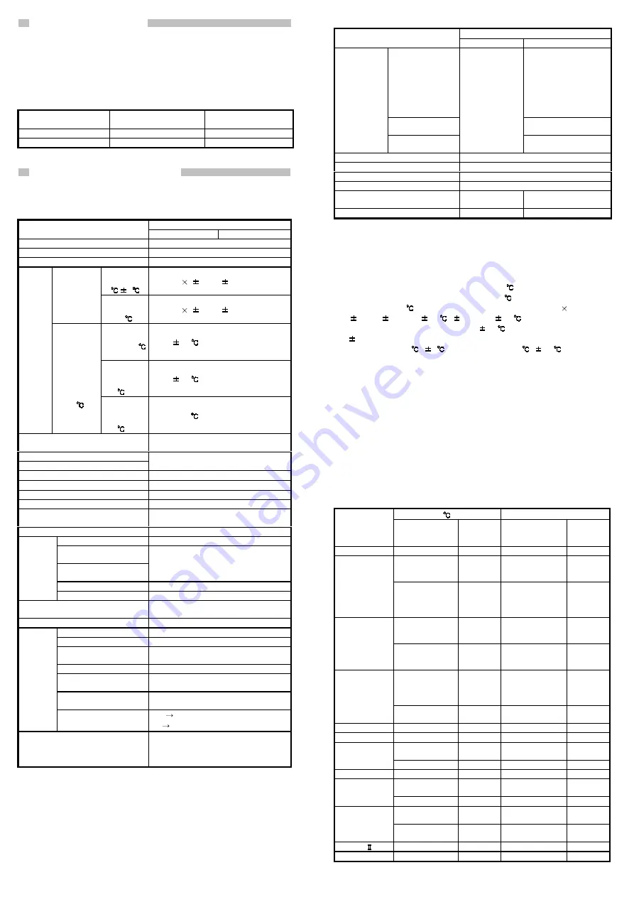
2. Performance Specification
The A1S62TC performance specification is indicated in Table 2.1.
Table 2.1 A1S62TC performance specification
Specification
Item
A1S62TCTT-S2
A1S62TCTTBW-S2
Control output
Transistor output
Temperature input points
2-channel/module
Supported thermocouple
Refer to Table 2.2.
Ambient
temperature:
23
5
Full scale
(
0.3%)
1 digit*2
Specification
accuracy
Ambient
temperature:
0 to 55
Full scale
(
0.7%)
1 digit*2
Temperature
measurement
value: -100
or higher
Within
1.0
Temperature
measurement
value: -150 to
-100
Within
2.0
Accuracy
*1
Cold-junction
compensation
temperature
accuracy
(ambient
temperature:
0 to 55
)
Temperature
measurement
value: -200 to
-150
- 3.0
Sampling period
0.5s/2-channel (It is not connected with the
number of channels used)
Heating control output period
Cooling control output period
1 to 100s
Influence on external resister
0.35
µ
V/
Ω
Input impedance
1M
Ω
Input filter
0 to 100s (0: input filter off)
Sensor compensation value setting
-50.00 to 50.00%
Operation when sensor input is
disconnected
Upscale processing
Temperature control method
PID on/off pulse
PID constant setting
Auto-tuning setting is possible
Heating proportional band
(Ph)
Cooling proportional band
(Pc)
0.1 to 1000.0%
Integral time (I)
1 to 3600s
PID
constant
range
Derivative time (D)
0 to 3600s (0: PI control)
Set value setting range
Within the temperature range set by the
thermocouple to be used.
Cooling method setting
Air cooling/water cooling
Output signal
ON/OFF pulse
Rated load voltage
10.2 to 30.0VDC (peak voltage : 30.0VDC)
Maximum load current
0.1A/1 point
0.4A/common
Maximum inrush current
0.4A 10ms
Maximum current when
OFF
Less than 0.1mA
Maximum voltage drop
when ON
1.0VDC (TYP) 0.1A
2.5VDC (MAX) 0.1A
Transistor
output
Response time
OFF
ON: Less than 2ms
ON
OFF: Less than 2ms (resistor load)
Insulation method
Between the input and grounding:
transformer insulation
Between the input and channel:
transformer insulation
Table 2.1 A1S62TC performance specification (continued)
Specification
Item
A1S62TCTT-S2
A1S62TCTTBW-S2
Current sensor
URD manufactured
current sensor*3
CTL-12-S36-8
(0.0 to 100.0A)
CTL-6-P-H
(0.00 to 20.00A)
(Former model, CTL-6-P
is also applicable.)
Input method
Multiplex method A/D
conversion
Heater wire
breakage
disconnection
specification
Number of alert
delays
-
3 to 255
I/O occupied points
Special 32 points
Connection terminal
20 points terminal block
Supported cable size (mm) [inch]
0.75 to 1.5 [0.030 to 0.059]
Supported solder-less terminal
R1.25-3, 1.25-YS3, RAV1.25-3, V1.25-YS3A
Internal consumed current (5VDC)
[A]
0.19
0.28
Weight (kg) [lb]
0.25 [0.55]
0.28 [0.62]
For the noise resistance, dielectric withstand voltage, and insulation
resistance for the PC system which uses this module, refer to the power
module specification found in the CPU Module User’s Manual.
*1: Calculate the accuracy as follows:
(Accuracy) = (specification accuracy) + (cold-junction temperature
compensation accuracy)
Example: When measuring the temperature 300
with the input range setting
“38 (the thermocouple K, -200.0 to 400.0, in 0.1
unit)” at ambient
temperature of 35
, the accuracy is: (400.0-(-200.0))[full scale]
(
0.007)[
0.7%] + (
0.1
)[
1 digit] + (
1.0
)[cold-junction
temperature compensation accuracy] =
5.3
*2: “
1 digit” error depends on the input range.
For setting unit of 1
,
1
For setting unit of 0.1
,
0.1
*3: Only the URD International, Ltd. current sensor can be used.
Sales channels for current sensors manufactures by URD International Ltd. are
listed as follows:
U.S.A.
Julia Industries Inc.
Tel:949-831-0111
BRAZIL
Ananda Industial Ltda.
Tel:011-5584-0959
UNITED
KINGDOM Omni Components
Tel:024-7622-5757
GERMANY Allied Electronics GmbH
Tel:0221-497-3084
FRANCE
Diltronic S.A.
Tel:01-34-51-33-00
ITALY
ELNET s.n.c.
Tel:041-50-19-939
KOREA
Joyang Trading Co.
Tel:02-521-2294
Sewon Tech Co.,Ltd.
Tel:02-868-9355/9356
Keum Ho Corporation
Tel:51-319-4155/4156
HONG-KONG Weltronics Components Ltd.
Tel:2410-0623
TAIWAN
Tope Co.,Ltd.
Tel:886-2-8228-0658
INDIA
AmtechElectronics PVT.Ltd.
Tel:02712-25324
Table 2.2 The types of supported thermocouple type and the
measured temperature range
°
F
Thermocouple
type
Measured
temperature
range
Data
resolution
Measured
temperature
range
Data
resolution
R
0 to 1700
1
0 to 3000
1
0 to 500
0 to 800
0 to 1300
1
0 to 1000
0 to 2400
1
K
-200.0 to 400.0
0.0 to 400.0
0.0 to 500.0
0.0 to 800.0
0.1
0.0 to 1000.0
0.1
0 to 500
0 to 800
0 to 1200
1
0 to 1000
0 to 1600
0 to 2100
1
J
0.0 to 400.0
0.0 to 500.0
0.0 to 800.0
0.1
0.0 to 1000.0
0.1
-200 to 400
-200 to 200
0 to 200
0 to 400
1
0 to 700
-300 to 400
1
T
-200.0 to 400.0
0.0 to 400.0
0.1
0.0 to 700.0
0.1
S
0 to 1700
1
0 to 3000
1
B
0 to 1800
1
0 to 3000
1
0 to 400
0 to 1000
1
0 to 1800
1
E
0.0 to 700.0
0.1
-
-
N
0 to 1300
1
0 to 2300
1
0 to 400
-200 to 200
1
0 to 700
-300 to 400
1
U
0.0 to 600.0
0.1
-
-
0 to 400
0 to 900
1
0 to 800
0 to 1600
1
L
0.0 to 400.0
0.0 to 900.0
0.1
-
-
PL
0 to 1200
1
0 to 2300
1
W5Re/W26Re
0 to 2300
1
0 to 3000
1
For the general specifications, refer to the User’s Manual for the PC
CPU used.


