5 - 164
MELSEC-A
5 DATA USED FOR POSITIONING CONTROL
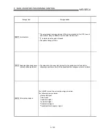
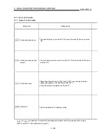
Storage item
Storage details
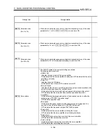
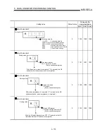
Md.113
Parameter error
(No.1 to 15)
•
When a servo parameter error occurs, the bit corresponding to any of the servo
parameter No. 1 to 15 (
Pr.101
to
Pr.115
) in error turns ON.
Md.114
Parameter error
(No.16 to 31)
•
When a servo parameter error occurs, the bit corresponding to any of the servo
parameter No. 16 to 31 (
Pr.116
to
Pr.131
) in error turns ON.
Md.115
Parameter error
(No.32 to 36)
•
When a servo parameter error occurs, the bit corresponding to any of the servo
parameter No. 32 to 36 (
Pr.132
to
Pr.136
) in error turns ON.
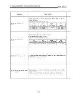
Md.116
Servo status
•
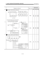
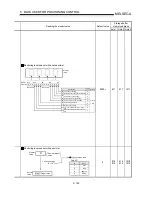
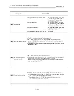
The ON/OFF states of the servo status flags are stored.
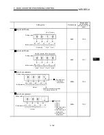
The following data are stored.
•
READY ON
Indicates the ready status of the servo amplifier.
ON indicates that the servo amplifier is ready, and OFF indicates that the servo
amplifier is not ready.
•
Servo ON
Indicates the servo ON status.
ON indicates servo ON, and OFF indicates servo OFF.
•
Zero point pass
Indicates whether the zero point (Z phase) of the pulse encoder installed on the
servomotor has been passed or not after a start.
ON indicates that the zero point has been passed at least once after a start.
OFF indicates that the zero point has never been passed after a start.
•
In-position
ON indicates that the droop pulse value of the deviation counter is within the
setting range of "
Pr.120
In-position range".
OFF indicates any other case.
•
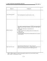
Zero speed
ON indicates the speed (speed at which the motor speed is judged as 0) is
equal to or lower than the speed set in "
Pr.130
Zero speed".
OFF indicates that the speed is higher than the zero speed.
•
Torque limit
ON indicates that the servo amplifier is limiting the torque.
OFF indicates that the servo amplifier is not limiting the torque.
•
Servo alarm
ON indicates that an alarm has occurred in the servo amplifier.
OFF indicates that no alarm has occurred.
•
Servo warning
ON indicates that a warning has occurred in the servo amplifier.
OFF indicates that no warning has occurred.
Summary of Contents for A1SD75M1
Page 2: ......
Page 20: ...A 18 MEMO...
Page 22: ...MEMO...
Page 27: ...1 5 MELSEC A 1 PRODUCT OUTLINE MEMO...
Page 42: ...1 20 MELSEC A 1 PRODUCT OUTLINE MEMO...
Page 52: ...2 10 MELSEC A 2 SYSTEM CONFIGURATION MEMO...
Page 111: ...5 21 MELSEC A 5 DATA USED FOR POSITIONING CONTROL MEMO...
Page 115: ...5 25 MELSEC A 5 DATA USED FOR POSITIONING CONTROL MEMO...
Page 123: ...5 33 MELSEC A 5 DATA USED FOR POSITIONING CONTROL MEMO...
Page 127: ...5 37 MELSEC A 5 DATA USED FOR POSITIONING CONTROL MEMO...
Page 167: ...5 77 MELSEC A 5 DATA USED FOR POSITIONING CONTROL MEMO...
Page 193: ...5 103 MELSEC A 5 DATA USED FOR POSITIONING CONTROL MEMO...
Page 276: ...5 186 MELSEC A 5 DATA USED FOR POSITIONING CONTROL MEMO...
Page 332: ...7 18 MELSEC A 7 MEMORY CONFIGURATION AND DATA PROCESS MEMO...
Page 334: ...MEMO...
Page 422: ...9 64 MELSEC A 9 MAIN POSITIONING CONTROL MEMO...
Page 446: ...10 24 MELSEC A 10 ADVANCED POSITIONING CONTROL MEMO...
Page 472: ...11 26 MELSEC A 11 MANUAL CONTROL MEMO...
Page 576: ...12 104 MELSEC A 12 CONTROL AUXILIARY FUNCTIONS MEMO...
Page 745: ......

