7 - 17
MELSEC-A
7 MEMORY CONFIGURATION AND DATA PROCESS
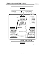
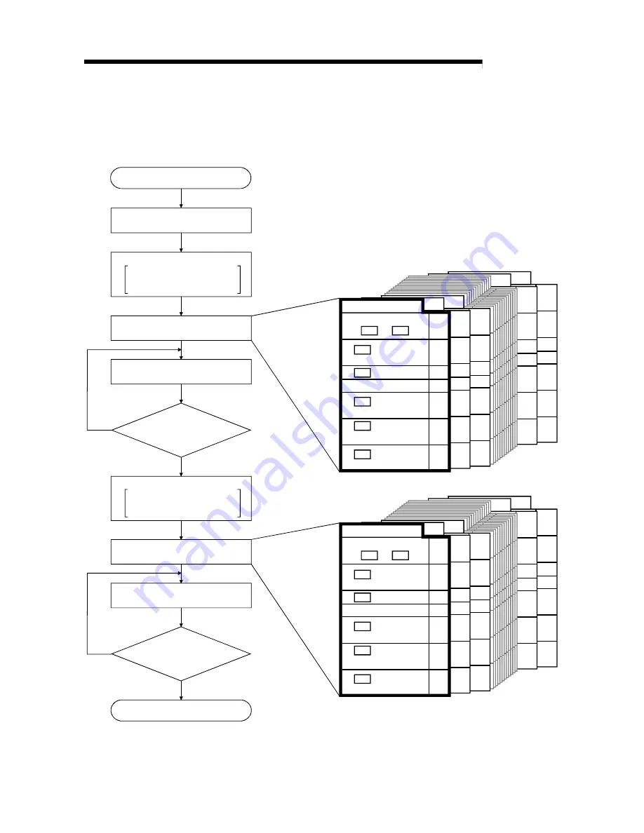
(Example) When setting the positioning data No. 101 to 300 of axis 1 to the OS
memory
(The number of data that can be set for block transmission at one time is up to 100
pieces.)
Set "2" to the buffer
memory address 5103.
Write is complete when the buffer
memory address 5103 turns to "0".
Set "1" to the buffer memory address
5100, "201" to the buffer memory
address 5101, and "100" to the buffer
memory address 5102.
Write is complete when the buffer
memory address 5103 turns to "0".
Set "2" to the buffer
memory address 5103.
6090
6091
6092
6094
6095
6096
6097
6098
6099
6100
6101
6102
6104
6105
6106
6107
6108
6109
200
199
6093
6103
103
102
Da.1 to Da.4
Da.5
Da.6
Da.7
Da.9
5120
5121
5122
5124
5125
5126
5127
5128
5129
5130
5131
5132
5134
5135
5136
5137
5138
5139
Positioning data No. 101
Arc address
M code
Dwell time
Command speed
Positioning address
/movement amount
Positioning identifier
Da.8
5123
5133
Not used
5110
5111
5112
5114
5115
5116
5117
5118
5119
5113
End
Turn OFF the PLC READY signal
[Y1D].
Set as follows.
Target axis: Axis 1
Head positioning data No.: 101
No. of read/write data: 100
Set the positioning data No. 101 to 200
to the read/write block.
Set as follows.
[Read/write request: Write request]
Is write complete?
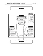
Set as follows.
Target axis: Axis 1
Head positioning data No.: 201
No. of read/write data: 100
Set the positioning data No. 201 to 300
to the read/write block.
Set as follows.
[Read/write request: Write request]
Start
Is write complete?
Set "1" to the buffer memory address
5100, "101" to the buffer memory
address 5101, and "100" to the buffer
memory address 5102.
6090
6091
6092
6094
6095
6096
6097
6098
6099
6100
6101
6102
6104
6105
6106
6107
6108
6109
300
299
6093
6103
203
202
Da.1 to Da.4
Da.5
Da.6
Da.7
Da.9
5120
5121
5122
5124
5125
5126
5127
5128
5129
5130
5131
5132
5134
5135
5136
5137
5138
5139
Positioning data No. 201
Arc address
M code
Dwell time
Command speed
Positioning address
/movement amount
Positioning identifier
Da.8
5123
5133
Not used
5110
5111
5112
5114
5115
5116
5117
5118
5119
5113
No
Yes
No
Yes
Summary of Contents for A1SD75M1
Page 2: ......
Page 20: ...A 18 MEMO...
Page 22: ...MEMO...
Page 27: ...1 5 MELSEC A 1 PRODUCT OUTLINE MEMO...
Page 42: ...1 20 MELSEC A 1 PRODUCT OUTLINE MEMO...
Page 52: ...2 10 MELSEC A 2 SYSTEM CONFIGURATION MEMO...
Page 111: ...5 21 MELSEC A 5 DATA USED FOR POSITIONING CONTROL MEMO...
Page 115: ...5 25 MELSEC A 5 DATA USED FOR POSITIONING CONTROL MEMO...
Page 123: ...5 33 MELSEC A 5 DATA USED FOR POSITIONING CONTROL MEMO...
Page 127: ...5 37 MELSEC A 5 DATA USED FOR POSITIONING CONTROL MEMO...
Page 167: ...5 77 MELSEC A 5 DATA USED FOR POSITIONING CONTROL MEMO...
Page 193: ...5 103 MELSEC A 5 DATA USED FOR POSITIONING CONTROL MEMO...
Page 276: ...5 186 MELSEC A 5 DATA USED FOR POSITIONING CONTROL MEMO...
Page 332: ...7 18 MELSEC A 7 MEMORY CONFIGURATION AND DATA PROCESS MEMO...
Page 334: ...MEMO...
Page 422: ...9 64 MELSEC A 9 MAIN POSITIONING CONTROL MEMO...
Page 446: ...10 24 MELSEC A 10 ADVANCED POSITIONING CONTROL MEMO...
Page 472: ...11 26 MELSEC A 11 MANUAL CONTROL MEMO...
Page 576: ...12 104 MELSEC A 12 CONTROL AUXILIARY FUNCTIONS MEMO...
Page 745: ......


