12 - 66
MELSEC-A
12 CONTROL AUXILIARY FUNCTIONS
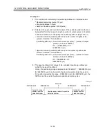
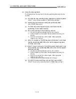
[2] Control details
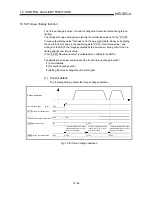
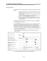
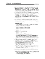
The operation performed for absolute position restoration mode switching is described
below.
1)
To switch the absolute position restoration mode, select the mode in
"
Pr.59
Absolute position restoration selection" and make a machine
zero point return.
The absolute position restoration mode is established when the zero
point return complete flag (
Md.40
Status: b4) turns ON.
2)
When power is switched from OFF to ON after execution of Step 1),
the system starts up in the mode established in Step 1) and restores
the absolute position.
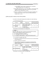
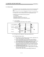
The established absolute position restoration mode can be checked in the "
Md.121
Absolute position restoration mode".
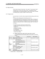
When the "
Md.121
Absolute position restoration mode" is "1: Infinite length mode", the
AD75 automatically updates the absolute position of the zero point stored in the
FeRAM every time the machine moves the given distance* (servomotor shaft: 8142 to
8192 revolutions). This detects the absolute position for infinite length positioning
control. Every time the absolute position is automatically updated, the "
Md.120
FeRAM
access count" is incremented by "2".
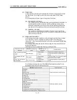
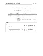
* The given distance is automatically determined by the setting of "
Pr.2
No. of
pulses per rotation".
Md.40
Zero point return complete flag
Status: b4
Machine zero point return start
(Positioning start signal) [Y10,Y11,Y12]
OFF
ON
OFF
OFF
ON
Standing by
In zero point return
Zero point return request flag
Status: b3
Md.40
Standard mode
OFF
ON
Standard mode
Infinite length mode
AD75 READY signal [X0]
PLC READY signal [Y1D]
ON
OFF
ON
Infinite length mode
Pr.59 Absolute position
restoration selection
Axis operation status
Md.35
Absolute position restoration
mode
Md.121
Standing by
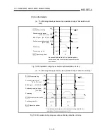
Fig. 12.34 Absolute position restoration mode switching operation
Summary of Contents for A1SD75M1
Page 2: ......
Page 20: ...A 18 MEMO...
Page 22: ...MEMO...
Page 27: ...1 5 MELSEC A 1 PRODUCT OUTLINE MEMO...
Page 42: ...1 20 MELSEC A 1 PRODUCT OUTLINE MEMO...
Page 52: ...2 10 MELSEC A 2 SYSTEM CONFIGURATION MEMO...
Page 111: ...5 21 MELSEC A 5 DATA USED FOR POSITIONING CONTROL MEMO...
Page 115: ...5 25 MELSEC A 5 DATA USED FOR POSITIONING CONTROL MEMO...
Page 123: ...5 33 MELSEC A 5 DATA USED FOR POSITIONING CONTROL MEMO...
Page 127: ...5 37 MELSEC A 5 DATA USED FOR POSITIONING CONTROL MEMO...
Page 167: ...5 77 MELSEC A 5 DATA USED FOR POSITIONING CONTROL MEMO...
Page 193: ...5 103 MELSEC A 5 DATA USED FOR POSITIONING CONTROL MEMO...
Page 276: ...5 186 MELSEC A 5 DATA USED FOR POSITIONING CONTROL MEMO...
Page 332: ...7 18 MELSEC A 7 MEMORY CONFIGURATION AND DATA PROCESS MEMO...
Page 334: ...MEMO...
Page 422: ...9 64 MELSEC A 9 MAIN POSITIONING CONTROL MEMO...
Page 446: ...10 24 MELSEC A 10 ADVANCED POSITIONING CONTROL MEMO...
Page 472: ...11 26 MELSEC A 11 MANUAL CONTROL MEMO...
Page 576: ...12 104 MELSEC A 12 CONTROL AUXILIARY FUNCTIONS MEMO...
Page 745: ......

