background image


A-4


 CONTENTS 


1. Overview ........................................................................................................1 
2. Specifications .................................................................................................1 

2.1 General Specifications..............................................................................1 
2.2 Performance specifications.......................................................................2 

3. Part Names ....................................................................................................3 
4. Handling Precautions .....................................................................................5 
5. Wiring.............................................................................................................6 

5.1 External wiring ..........................................................................................6 
5.2 Connection and wiring of the connector for I/O interface...........................7 

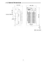
6. External Dimensions ......................................................................................8 


Summary of Contents for CL2XY16-DTP1C5V

Page 1: ...rdware Thank you very much for purchasing this product Please read this manual thoroughly before starting to use the product and handle the product properly MODEL CL2XY16 DTP1C5V U MODEL CODE 13JP27 I...

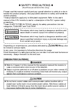
Page 2: ...ed out properly Depending on circumstances procedures indicated by CAUTION may also be linked to serious results In any case it is important to follow the directions for usage Store this manual in a s...

Page 3: ...iring may cause fire and or product failure z Make sure foreign objects do not get inside the module such as dirt and wire chips It may cause fire product failure or malfunction STARTING AND MAINTENAN...

Page 4: ...ting This manual confers no industrial property rights or any rights of any other kind nor does it confer any patent licenses Mitsubishi electric Corporation cannot be held responsible for any problem...

Page 5: ...fications 1 2 1 General Specifications 1 2 2 Performance specifications 2 3 Part Names 3 4 Handling Precautions 5 5 Wiring 6 5 1 External wiring 6 5 2 Connection and wiring of the connector for I O in...

Page 6: ...ing to JIS B 3502 IEC 61131 2 147 m s2 3 times in each of 3 directions X Y Z Operating ambience No corrosive gases Operating altitude 2000m 6562ft max Installation location Inside control panel 3 Over...

Page 7: ...0 5ms 1 5ms 1 5ms Standard type ON OFF 0 5ms or lower Resistive load Input method Positive common Surge suppression Zener diode Common wiring method 8 points 1 common sensor connector 3 wire type Com...

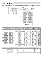
Page 8: ...2 V 2 V 2 NC 2 NC 3 24G 3 24G 3 NC 3 NC CON1 4 X0 CON5 4 X4 CON 9 4 Y0 CON 13 4 Y4 1 24V 1 24V 1 24V 1 24V 2 V 2 V 2 NC 2 NC 3 24G 3 24G 3 NC 3 NC CON2 4 X1 CON6 4 X5 CON 10 4 Y1 CON 14 4 Y5 1 24V 1 2...

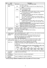
Page 9: ...ation stops The switch is set to OFF at shipment from the factory ON Maintain output OFF Turn output off 3 Response time setting switch SW8 Set the response time OFF ON ON OFF time of the remote I O m...

Page 10: ...crews using a pitch of 200mm 7 87in or less when attaching a DIN rail 2 To attach the remote I O module to the DIN rail press the centerline area of the DIN rail hook beneath the module until a click...

Page 11: ...24G X1 1 2 3 4 CON2 24V V 24G X7 1 2 3 4 CON8 1 2 3 4 Connector for CC Link LT interface Insulation Connector for I O interface Constant voltage circuit 3 wire sensor Sink output NPN output type Sink...

Page 12: ...und the cable cannot be inserted smoothly Cut the cable tip using pliers etc and make it as round as possible then insert it y When inserting the cable the cable may stick out from the front of the co...

Page 13: ...ns 48 1 89 No IN OUT CL2XY16 DTP1C5V PW L RUN L ERR LINK PW ON 8 7 6 5 4 3 2 1 ST 9 7 6 5 4 3 2 1 0 7 6 5 4 3 2 1 0 X 0 1 2 3 4 5 6 7 Y 0 1 2 3 4 5 6 7 39 1 54 85 3 35 4 0 16 43 1 69 4 0 16 Center of...

Page 14: ...lles Barcelona Spain Tel 34 93 565 3131 France Mitsubishi Electric Europe B V French Branch 25 Boulevard des Bouvets F 92741 Nanterre Cedex France TEL 33 1 5568 5568 South Africa Circuit Breaker Indus...

Reviews: