background image

DIGITAL COLOR PRINTER

MODEL

CP770DW

OPERATION MANUAL

THIS OPERATION MANUAL IS IMPORTANT 

TO YOU.

PLEASE READ IT BEFORE USING YOUR 

DIGITAL COLOR PRINTER.

POWER

OPEN

COPY             ONLINE

CP770DW 

PAPER  FEED

 &CUT

ALARM

SHEET/PAPER

SCSI

DATA

This  digital color printer complies with the requirements of the EC

Directive 89/336/EEC, 73/23/EEC, 93/42/EEC and 93/68/EEC.

The electro-magnetic susceptibility has been chosen at a level that

gains  proper operation in residential areas, on business and light

industrial premises and on small-scale enterprises, inside as well as

outside of the buildings.  All places of operation are characterised by

their connection to the public low voltage power supply system.

Summary of Contents for CP-770DW

Page 1: ...ter complies with the requirements of the EC Directive 89 336 EEC 73 23 EEC 93 42 EEC and 93 68 EEC The electro magnetic susceptibility has been chosen at a level that gains proper operation in residential areas on business and light industrial premises and on small scale enterprises inside as well as outside of the buildings All places of operation are characterised by their connection to the pub...

Page 2: ...the host equipment The AC power cord should be UL or CSA approved and consist of type SJT size 16 or 18AWG length 2 5m or shorter cord with IEC320 C13 type 250V 10A or higher rating connector and IEC320 2 2 E type 250V 10A or higher rating plug CAUTION Changes or modifications not expressly approved by the party responsible for compliance could void the user s authority to operate the equipment NO...

Page 3: ... item may be hot and should not be touched The ON OFF symbol indicates connection to or disconnection from the mains at least for mains switches The Equipotentiality symbol identifies the terminals connected each other The poten tial of various parts of equipment or of a system is equalized The Alternating current symbol indicates that the equipment is suitable for alternating current only RISK OF...

Page 4: ...ize 1mm2 or bigger length 2 5m or shorter cord with IEC320 C13 type 250V 10A or higher rating connector and CEE 7 VII type or IEC 320 2 2 E type 250V 10A or higher rating plug Use the parallel cable according to the recommendations as below in order to comply with EN60601 1 2 The parallel cable with appropriate plug should be 2 m long or shorter comply with IEEE1284 standard shielded 62Ω impedance...

Page 5: ...al This page the previous pages for safety and page 23 for accessories This page the previous pages for safety and page 23 for accessories This page the previous pages for safety and page 23 for accessories Page 16 for print paper Page 24 for accessories WARNING The use of ACCESSORIES transducers and cables other than those specified with the exception of transducers and cables sold by the manufac...

Page 6: ...rt interruptions and voltage variations on power supply input lines IEC EN 61000 4 11 Power frequency 50 60 Hz magnetic field IEC EN 61000 4 8 IEC EN 60601 test level 6 kV contact 8 kV air 2 kV for power supply lines 1 kV for input output lines 1 kV differential mode 2 kV common mode 5 UT 95 dip in UT for 0 5 cycle 40 UT 60 dip in UT for 5 cycles 70 UT 30 dip in UT for 25 cycles 5 UT 95 dip in UT ...

Page 7: ...n electromagnetic site survey a should be less than the compliance level in each frequency range b Interference may occur in the vicinity of equipment marked with the following symbol Compliance level 3 Vrms 3 V m NOTE1 At 80 MHz and 800 MHz the higher frequency range applies NOTE2 These guidelines may not apply in all situations Electromagnetic propagation is affected by absorption and reflection...

Page 8: ... W 0 01 0 1 1 10 100 150 kHz to 80 MHz d 1 2 P 0 12 0 38 1 2 3 8 12 80 MHz to 800 MHz d 1 2 P 0 12 0 38 1 2 3 8 12 800 MHz to 2 5 GHz d 2 3 P 0 23 0 73 2 3 7 3 23 For transmitters rated at maximum output power not listed above the recommended separation distance d in meters m can be estimated using the equation applicable to the frequency of the transmitter where P is the maximum output power rati...

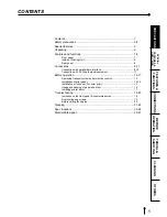
Page 9: ...nnection with parallel data interface 9 10 Connection with SCSI data signal equipment 11 Before operation 12 17 Removing transport screw and protective cushion 12 Installation of print paper 12 14 Installation of ink sheet For color print 15 Usage and keeping of paper sheet set 16 Installing printer driver 17 Troubleshooting 18 20 Indication on the front panel countermeasures 18 Overcoming paper j...

Page 10: ...e unit can cause serious damage to the unit and potential shock or fire danger If liquid is spilled into or seeps into the unit unplug the Power Cord immediately and seek service as soon as possible to avoid additional or possible damage due to corrosion In the interest of safety avoid handling of liquids near the unit DO NOT REMOVE THE CABINET THEREARE NO USER SERVICEABLE PARTS INSIDE AND YOU WIL...

Page 11: ...he unit and prevent operation Allow the temperature to stabilize before use OPERATING AMBIENT TEMPERATURE RANGE The operating temperature range is 41 F 104 F 5 C to 40 C and humidity of 20 80 When using the unit in a system rack make sure that the temperature inside the rack does not exceed this range FOR LONG OPERATING LIFE UNSUITABLE MATERIALS FOR THE PRINTER Paint coat flaking and plastic defor...

Page 12: ...lity and usability of device and accessories c Electrical test Testing of electrical safety of the system according to EN60601 1 High humidity or dust Avoid locations with high humidity and dust in order to avoid malfunctioning of the device Also avoid locations subject to corrosive gasses and smoke Heat Direct sunlight heaters or other heat sources may deform the housing and subsequently cause ma...

Page 13: ...ion thermal transfer color printer which produces superior high quality images It also produces a continuous tone at 256 gradient and 16 7 million colors for each YMC 325 PPI HIGH RESOLUTION CP770DW has a 325 PPI high resolution for precise illustrations and sharp photographic images MULTI AND WIDE PRINT FOR VARIOUS REQUIREMENTS OR APPLICATIONS 4 and 16 images of multi print and wide prints are av...

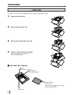
Page 14: ...cessory box 3 3 3 3 3 Remove the cushion above the unit 4 4 4 4 4 Take the unit out of the box carefully Make sure to keep the unit horizontally Then unwrap the packing 2 2 2 2 2ACCESSORY BOX CONTENTS 2 Power cords US and CE cables Ink cassette Operation manual Warranty card Sheet Installing print paper and ink sheet Printer driver CPD770W Spacer Thermal paper bobbins ...

Page 15: ...AMP Goes on and off during transferring data 6 6 6 6 6PAPER FEED CUT BUTTON Pressing this button the print paper is fed and cut When 8ON LINE lamp is lit this button is not functional 7 7 7 7 7COPY BUTTON When pressing this button the transferred data will be printed When 8ON LINE lamp is lit this button is not functional 8 8 8 8 8ONLINE BUTTON Press to switch the PC connection between ONLINE and ...

Page 16: ...REMOTE 1 INSIDE OF PRINTING UNIT 1 1 1 1 1SLIDE SWITCH Selects input PARALLEL and OPTION SCSI terminal input Default setting is OPTION When optional SCSI board is not installed PARALLEL is selected 2 2 2 2 2PAPER SENDING CONTROL Turn this control clockwise to rewind the print paper 3 3 3 3 3INK CASSETTE COMPARTMENT Load the cassette with ink sheet 4 4 4 4 4INK CASSETTE LOCKING LEVER Push this leve...

Page 17: ...used Set to Standard mode when using the printer driver supplied with this unit Set to Compatible mode 1 when using printer drivers CPD 04 CPD 05 for CP700DU DE and CP700DSU DSE To PARALLEL DATA IN PC MODE switches AC LINE PARALLEL DATA IN 1 2 3 4 5 6 7 8 OFF ON OFF 8 7 6 5 4 3 2 1 1 2 3 4 5 6 7 8 OFF ON OFF 1 2 3 4 5 6 7 8 No 1 No 2 No 6 Mode Details OFF OFF OFF Standard mode When printing with t...

Page 18: ...3 3 3 Confirm that the ON LINE button on the front panel is lit When ON LINE is selected the lamp illuminates NOTE You do not need to press the ONLINE button when it is already lit In the following conditions ON LINE lamp illuminates when turning on the power Installing printing paper and ink sheet Inserting printing unit correctly Available to receive the data POWER CP770DW PAPER FEED CUT COPY ON...

Page 19: ...ment the terminator is required SCSI ID switch 1 1 1 1 1 Connect the unit with PC through SCSI cable 2 2 2 2 2 Set the slide switch in the printing unit to OPTION SCSI 2 2 2 2 2SETTING SCSI ID SWITCHES Set the SCSI ID switches SCSI ID on the rear panel according to the connected equipment When shipping SCSI ID is set to No 5 No 7 is provided for personal computer you use and No 0 for built in hard...

Page 20: ... used during shipping or transport to avoid damage SCREW AC LINE PARALLEL DATA IN 1 2 3 4 5 6 7 8 OFF ON OFF 1 2 3 4 5 6 7 8 REMOTE Before printing 1 Remove the transport screw on the bottom of printing mechanism and the protective cushion See below 2 Install the print paper and ink cassette pages 13 15 Transport screw 2 2 2 2 2 REMOVING THE PROTECTIVE CUSHION Unplug the power cord from outlet for...

Page 21: ... cut it not to use sticky part Remove the sticky part dust or fingerprints on the paper 3 3 3 3 3Cut both edges of the paper NOTE Ink sheet is not needed for thermal printing The thermal paper setting is completed NOTE Sheet cartridge error appears when an ink sheet is installed though the printer driver selects thermal paper The error appears during data transfer and start of printing operation 2...

Page 22: ...e paper straight 5 5 5 5 5Feed the print paper through the paper outlet with your hand 6 6 6 6 6Pull the print paper to eliminate slack 7 7 7 7 7Move the knob on the side of the printing unit to the direction as indicated by the arrow NOTE If too much paper is fed ALARM lamp may light In this case press P APER FEED CUT button Print paper 1 3 2 Roller Roller Roller Paper Paper Paper ...

Page 23: ...NG THE INK SHEET Load the ink cassette with the ink sheet rolls before inserting the ink cassette into the unit 1 1 1 1 1Put the colored roller of the ink sheet to the ink cassette AB AB AB AB AB 2 2 2 2 2Put the thin stick of white roller to the ink cassette C C C C C 3 3 3 3 3Put the thick stick of white roller to the ink cassette DE DE DE DE DE On the Dposition turn the roller and set the notch...

Page 24: ...e print paper the number of prints per roll may be limited as specified on page 24 2 2 2 2 2 AFTER PRINTING When the printed paper is touched by a wet hand the print may be discolored Fading may occur if the print face is exposed to organic chemical agents which may affect print paper e g alcohol ester ketone based Fading will be accelerated upon contact with PVC based materials e g adhesive tapes...

Page 25: ...er for Windows is supplied with this unit Product name For Windows For Windows NT Operating conditions Applies for Microsoft Windows 95 and Windows 98 Applies for Microsoft Windows NT 4 0 Refer to the operation manual of the driver software or Read me for installing If you use Macintosh computer the optional SCSI board SB770 is needed Windows 95 Windows 98 and Windows NT are the registered tradema...

Page 26: ...ad becomes too high Wait until the message goes off Note 3 Paper jamming occurs Other defects Refer to Overcoming paper jams Make sure the ON LINE lamp is not lit and press PAPER FEED CUT button If the status is not improved by carrying out this measure consult your dealer Note 4 Note 1 The lamp goes on and off after transferring data and just before starting printing operation Note 2 In case of L...

Page 27: ...ton again 2 2 2 2 2Remove the ink cassette Unlock the ink cassette by pushing the cassette locking lever to inside Refer to Page 8 3 3 3 3 3 Turn the knob on the right side of the printing unit clockwise Roll up the print paper completely 4 4 4 4 4Remove the print paper 5 5 5 5 5Cut the defective part of the print paper with scissors 6 6 6 6 6Cut both edges of the print paper 7 7 7 7 7Install the ...

Page 28: ...t used up Check the status Is the printing unit set correctly Set the printing unit correctly The stored image in the memory cannot be Is the appropriate image data transferred enlarged to fill the maximum print area Is the printer driver set to the correct media size The image can not be transferred Is the ON LINE lamp lit Press the ON LINE button Is the slide switch in the printing unit set corr...

Page 29: ... OPEN button to pull the printing unit out 2 2 2 2 2Remove the ink cassette and print paper 3 3 3 3 3 Wipe the ink sheet sensor Clean the parts which the arrows show Wipe dust with cotton buds etc which is soaked in a small amount of alcohol 4 4 4 4 4 Wipe the ink sheet sensor reflection plate Clean the metal reflection plate Wipe with tissue paper etc which is soaked in a small amount of alcohol ...

Page 30: ... 7 7 7 7 7Cleaning paper end sensor Wipe the dust with cotton buds which is soaked in a small amount of alcohol 8 8 8 8 8 Cleaning rubber roller The seal paste and dust etc are stuck on the rubber roller if you use it for a long time Wipe with tissue paper etc which is soaked in a small amount of alcohol carefully 9 9 9 9 9 Cleaning print outlet The seal paste may be stick on the paper guide insid...

Page 31: ... roll paper S size 110 x 107mm Printing area S wide mode 104 8 x 75mm S mode 99 8 x 75mm Special roll paper L size 162 x 110mm Printing area L wide mode 130 x 104 8mm L mode 130 x 99 8mm Special roll paper LL size 182 x 110mm Printing area LL wide mode 150 x 104 8mm LL mode 150 x 99 8mm Supply method Automatic Input Output terminal Parallel data interface 36 pin female type Power supply AC 120V 50...

Page 32: ...NK CASSETTE AND INK SHEET Product name Ink sheet size No of prints Usage PKC700S S size 200 For 3 color use PKC700L L size 130 For 3 color use 2 2 2 2 2 SCSI BOARD SB770 By equipping the unit with the SCSI board the image data is sent by host CPU through SCSI II interface Note for wide printing When selecting wide mode S wide L wide and LL wide in print paper setting edge of the image may be cut d...

Page 33: ...CP PC VCP Function Strobe pulse for data reading Incoming pulse width should be 0 5µs minimum At regular conditions High data will be read after becoming Low High data 1 Low data 0 Information will be expressed for parallel data of every signal from bit No 1 to No 8 The signal is yielded after data input has ended by a data reception acknowledgement pulse High VCP data is not accepted Low VCP data...

Page 34: ...Active From To PC VCP PC VCP PC VCP PC VCP PC VCP PC VCP PC VCP PC VCP PC VCP PC VCP PC VCP Function High Unknown Sends data in Low when HostBusy is Low After HostBusy turns High this signal becomes High Data4 Data8 MSB Data3 Data7 Data2 Data6 High VCP is on BUSY status Low VCP can send data Earth PeripheralLogicHigh Earth Clears sending data to this unit Low Incoming pulse width should be 100µs m...

Page 35: ...PC VCP PC VCP PC VCP PC VCP PC VCP Function Forward data transfer Becomes Low when PeriphAck is Low and there is data to be read Returns to High when PeriphACK becomes High High data 1 Low data 0 Information will be expressed for parallel data of every signal from bit No 1 to No 8 Reverse data transfer Sends Low data when HostAck is Low Returns to High when HostAck becomes High Forward data transf...

Page 36: ... 2 Via Paracelso 12 20041 Agrate Brianza Milano Italy Phone 039 60531 FAX 039 6057694 Benelux Branch Nijverheidweg 23 A 3641 RP Postbus 222 3640 AE Mijdrecht Phone 0297 282461 FAX 0297 283936 Spanish Branch Barcelona Spanish Branch Barcelona Sucursal en españa Ctra Rubí 76 80 08190 Sant Cugat del Vallés Ap de Correos 420 BARCELONA SPAIN Phone 34 93 565 3154 FAX 34 93 589 4388 Made from recycled pa...

Reviews: