background image

FOREWORD 


This service manual describes the specifications as well as the maintenance and 

adjustment procedures for Mitsubishi diesel engines.    This manual also includes the 

detailed information on basic and special tools as the need arises. 


The Mitsubishi diesel engines can offer highly efficient and reliable performance for 

many years to come, which, however, only can be achieved through the proper 

handling and the periodical inspection

/

maintenance work exercised in according to 

the procedures of disassembly, inspection

/

adjustment and reassembly described in this 

manual. 


Before attempting any work on your engine, thoroughly read this manual to 

familiarize with the engine and the required procedures of the work. 


All information contained in this manual is based on the engine produced at the time 

of publication and is subject to change as the engine improved without notice. 

Pub. No. 99619-12140

Summary of Contents for diesel engines

Page 1: ...ch however only can be achieved through the proper handling and the periodical inspection maintenance work exercised in according to the procedures of disassembly inspection adjustment and reassembly described in this manual Before attempting any work on your engine thoroughly read this manual to familiarize with the engine and the required procedures of the work All information contained in this ...

Page 2: ... order of disassembly 2 Inspecting points during disassembly are shown in the Disassembly figures by enclosing in the box 3 Service standards for inspection and repair are listed on the appropriate pages of this manual where the relevant descriptions are made Also a comprehensive listing of service standards is provided in Group 1 4 Parts reassembly sequence is provided below the Figure of that re...

Page 3: ...Center BBDC Before Bottom Dead Center ABDC After Bottom Dead Center TIR Total Indicator Reading API American Petroleum Institute ASTM American Society for Testing and Materials JIS Japan Industrial Standards LLC Long Life Coolant MIL Military Specifications MSDS Material Safety Data Sheets SAE Society of Automotive Engineers 4 Units Values shown in this manual are based on SI units International S...

Page 4: ...ATION 4 9 COOLING SYSTEM REMOVAL 5 1 COOLING SYSTEM DISASSEMBLY INSPECTION AND REASSEMBLY 5 5 5 Cooling System COOLING SYSTEM INSTALLATION 5 9 INLET AND EXHAUST SYSTEMS REMOVAL 6 1 INLET AND EXHAUST SYSTEMS DISASSEMBLY INSPECTION AND REASSEMBLY 6 5 6 Inlet and Exhaust Systems INLET AND EXHAUST SYSTEMS INSTALLATION 6 7 ELECTRICAL SYSTEM REMOVAL 7 1 ELECTRICAL SYSTEM DISASSEMBLY INSPECTION AND REASS...

Page 5: ......

Page 6: ...on Use correct engine oil and LLC 0 5 Only use the specified fuel engine oil and coolant LLC 0 5 Handle LLC with care 0 5 Lawful disposal of waste oil and coolant 0 5 Caution Handling of battery 0 6 Handle the battery with care 0 6 Caution How to handle emergencies 0 6 Engine overheat Idle to cool down then stop the engine 0 6 Never restart the engine after a sudden stop unless the cause is elimin...

Page 7: ...east 10 minutes until the engine has sufficiently cooled down If fresh air flows into the crankcase with the engine still hot the remaining mist of oil may ignite and cause explosion Pay attention to fuel and oil leakage If leakage of fuel or oil is found immediately take measures to stop it If leaking fuel or engine oil spills over the heated engine fire may start possibly leading to bodily injur...

Page 8: ...ating parts that are likely to be caught by these parts Should any part of human body or tool is caught by the rotating parts dismemberment or other bodily injury will result Lockout tagout Perform lockout tagout before carrying out any inspection service Lockout tagout is an ideal way of disconnecting the machine equipment from the power source To lockout tagout remove the starter switch key plac...

Page 9: ...topped Replenish coolant when the coolant in the system is sufficiently cold Otherwise you may become burned Do not remove heat insulating material The exhaust system components become extremely hot and therefore are covered with heat insulating material Never remove the material If the material needs to be removed at all for inspection service be sure to install it again after the operation Warni...

Page 10: ...the engine or other areas of the engine difficult to reach Do not use a rickety stool nor substitute a box of parts Otherwise you may fall and become injured Do not leave anything on the stool Caution Use correct engine oil and LLC Only use the specified fuel engine oil and coolant LLC Only use the fuel engine oil and coolant LLC that are specified in this manual Handle them with sufficient care U...

Page 11: ...a with plenty of water and then thoroughly clean with soap Should your eyes come into contact with battery electrolyte loss of eyesight may result Immediately wash your eyes with plenty of fresh water and seek medical attention immediately Should you inadvertently drink battery electrolyte repeatedly gargle with plenty of water and then drink plenty of water Seek medical attention immediately Caut...

Page 12: ...ngine by running it at low idle for 5 to 10 minutes Warming up the engine will not only smoothen the operation of various engine parts but also help extend its service life It also helps maximize the performance and achieve economical running of the engine Do not warm up the engine longer than necessary Doing so facilitates carbon deposit on the cylinders possibly leading to poor combustion Do not...

Page 13: ... engine and cause an accident When working jointly with other people on the same task use signals to coordinate actions involved Wear appropriate clothes and protective gear Whenever appropriate including when using compressed air wear protective gear such as helmet face mask safety shoes dust mask goggles and gloves Working without appropriate protective gear may lead to serious injury Use approp...

Page 14: ...3 Oil System Schematic 1 4 1 4 Cooling System Schematic 1 5 1 5 Inlet Exhaust System Schematic 1 5 1 6 Engine Serial Number 1 6 1 7 Engine Model and Application Codes 1 6 2 Specifications 1 7 3 Disassembly Reassembly Notes 1 9 3 1 Disassembly 1 9 3 2 Reassembly 1 9 GENERAL ...

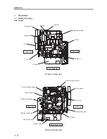
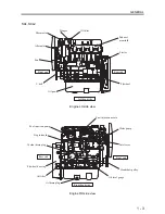
Page 15: ...and side Thermostat Hanger Alternator Fan V belt Oil pan Flywheel Engine LH side view Right hand side Fuel injection nozzle Fuel injection pump Water pump Stop solenoid Coolant drain plug Flywheel housing Oil level gauge Oil filter Oil drain plug Inlet cover Crankshaft pulley Front end Rear end Engine RH side view ...

Page 16: ...tat Hanger Alternator Fan V belt Oil pan Flywheel Engine LH side view Right hand side Fuel injection nozzle Fuel injection pump Water pump Stop solenoid Coolant drain plug Flywheel housing Oil level gauge Oil filter Oil drain plug Inlet cover Crankshaft pulley Front end Rear end Engine RH side view ...

Page 17: ... pump Fuel filter Fuel leak off pipe Fuel injection pipe Fuel injection nozzle Fuel injection pump O P E N Fuel system schematic 1 3 Oil System Schematic Oil pressure switch Oil main gallery Oil filter Relief valve Oil pump Oil drain plug Oil strainer Oil system schematic ...

Page 18: ...e Thermostat Cooling fan Cooling system schematic 1 5 Inlet Exhaust System Schematic Exhaust gas Intake air Exhaust gas to muffler Air breather pipe positive crankcase ventilation Blow by gas Intake air from air cleaner Inlet cover Exhaust manifold Inlet exhaust system schematic ...

Page 19: ...des 1 The engine model code is embossed on the side of the fuel injection pump mount on the right hand side of the cylinder block 2 The engine model code consists of the following alphanumerical digits Model coding Example S 4 L 2 Type 2 Type 2 Series L bore size 78 mm 3 07 in No of cylinders 4 4 cylinders S Sagamihara Machinery Works Engine model code Engine serial number location Engine serial n...

Page 20: ...TDC 15 Inlet valve Close ABDC 41 Open BBDC 54 Valve timing hot engine Exhaust valve Close ATDC 10 Engine mounting 4 mounts Engine main parts Starting method Starter Type Bosch M Manufacturer DENSO Plunger diameter mm in φ5 5 0 21 MS retard crank angle 8 Injection pump Cam lift mm in 15 0 59 Governor Governing method Centrifugal fly weight type Type Throttle nozzle Manufacturer Bosch Automotive Sys...

Page 21: ...on Output V kW 12 V 1 7 12 V 2 0 24 V 3 2 No of units 1 Starter Reduction ratio pinion ring gear 13 120 Type 3 phase alternator w built in IC regulator Manufacturer Mitsubishi Electric Corporation Output V A 12 50 24 25 Speed at which rated voltage is generated min 1 5000 13 5 V 47 A 5000 27 0 V 22 A Alternator Regulated voltage V 14 7 0 3 12 50 26 5 0 5 24 25 Type Sheathed plug 12 V plug 24 V plu...

Page 22: ...uence given in the manual 3 As parts are disassembled place them neatly in the order of removal to eliminate missing parts on reassembly 4 During disassembly note the assembly marks Remember to respect these marks on reassembly Whenever appropriate put additional assembly marks to aid reassembly 5 Before and during disassembly as well as during subsequent washing carefully check for any abnormalit...

Page 23: ...ENERAL 1 10 4 Tighten hardware to the specified torque if provided in the manual Be sure to use a torque wrench 5 Gaskets packing and O rings should be replaced with new parts unless specified otherwise ...

Page 24: ...Table 1 12 2 Tightening Torques Table 1 16 2 1 Major Bolts and Nuts 1 16 2 2 Standard Bolts and Nuts 1 17 2 3 Standard Eyebolts 1 17 2 4 Standard Union Nuts 1 18 2 5 Taper Bolts 1 18 3 Sealants List 1 19 SERVICE STANDARDS ...

Page 25: ...timing BTDC 17 Rocker arm inner diameter φ19 0 749 18 910 to 18 930 0 7450 to 0 7458 Rocker shaft diameter φ19 0 749 18 880 to 18 898 0 7438 to 0 7445 Rocker Arm to shaft clearance oil clearance 0 012 to 0 050 0 0004 to 0 0019 0 200 0 0079 Replace rocker arm Inlet φ6 6 0 260 6 565 to 6 580 0 2586 to 0 2592 6 500 0 256 Valve stem diameter Exhaust φ6 6 0 260 6 530 to 6 550 0 2572 to 0 2580 6 500 0 2...

Page 26: ...1 78 05 3 075 Diameter 0 50 OS 78 50 3 09 78 43 to 78 45 3 090 to 3 090 78 30 3 085 Max allowable variation in weight among pistons on the same engine 5 g 0 177 oz or less Piston pin diameter φ23 0 9062 22 944 to 23 000 0 9039 to 0 9062 Piston pin to boss clearance 0 006 to 0 018 0 0002 to 0 0007 0 050 0 002 Piston Piston to cylinder clearance 0 035 to 0 086 0 0014 to 0 0034 0 300 0 012 Bore or re...

Page 27: ...394 34 720 1 3679 Replace Fuel injection pump shaft cam height including lobe 44 0 1 1 7336 0 0039 43 1 6942 Replace Flywheel flatness 0 150 0 0059 or less 0 500 0 0197 Correct Tappet to guide clearance 0 150 0 0059 Replace tappet Camshaft journal to bushing clearance 0 050 to 0 125 0 0020 to 0 0049 0 150 0 0059 Replace bushing Engine main parts Idler gear to shaft clearance 0 020 to 0 070 0 0008 ...

Page 28: ...load 17 5 to 23 7 N 1 78 to 2 41 kgf 3 9 to 5 3 lbf 29 4 to 39 2 N 3 0 to 4 0 kgf 6 6 to 8 8 lbf 6 90 N 0 70 kgf 1 6 lbf 13 7 N 1 40 kgf 3 1 lbf Replace Commutator radial runout 0 05 0 002 0 03 0 001 0 10 0 004 Correct or replace Commutator diameter 29 4 1 16 32 0 1 26 28 8 1 13 31 4 1 24 Replace Starter Mica undercutting depth 0 5 0 02 0 2 0 01 Correct A007T02071C A007TA8571 IC regulator controll...

Page 29: ...58 8 5 0 to 6 0 36 2 to 43 4 Fuel injection pipe nut M12 1 5 24 5 to 34 3 2 5 to 3 5 18 1 to 25 3 Fuel leak off pipe nut M12 1 5 20 6 to 24 5 2 1 to 2 5 15 2 to 18 1 Sliding sleeve shaft M10 1 25 29 4 to 41 2 3 0 to 4 2 21 7 to 30 4 Torque spring set special nut M12 1 0 14 7 to 24 5 1 5 to 2 5 10 8 to 18 1 Oil system Oil relief valve M22 1 5 44 1 to 53 9 4 5 to 5 5 32 5 to 39 8 Oil pan drain plug ...

Page 30: ...and nuts b The values in the table apply when tightened together with spring washers c The above table shows standard values for which a tolerance of 10 is allowed d Unless otherwise specified standard bolts and nuts should be tightened to the torques in the table e Do not apply oil to threaded portions Tighten under dry conditions 2 3 Standard Eyebolts Property class Thread diameter pitch mm N m ...

Page 31: ...6 220 M33 1 5 245 25 180 7 254 M36 1 5 294 30 216 8 Dry conditions 2 5 Taper Bolts Tightening into aluminum Tightening into iron Size N m kgf m lbf ft N m kgf m lbf ft NPTF1 16 4 90 to 7 85 0 5 to 0 8 3 6 to 5 8 7 85 to 11 8 0 8 to 1 2 5 8 to 8 7 PT1 8 7 85 to 11 8 0 8 to 1 2 5 8 to 8 7 14 7 to 21 6 1 5 to 2 2 10 8 to 15 9 PT1 4 NPTF1 4 19 6 to 29 4 2 0 to 3 0 14 5 to 21 7 34 3 to 44 1 3 5 to 4 5 ...

Page 32: ...nd 1212 Governor case Threaded portion Cylinder block Cylinder head Sealing cap Cylinder head Cylinder block Expansion plug Holes in the cylinder head and block Press fit part Oil level gauge guide ThreeBond 1102 Cylinder block Side seal Cylinder block Main bearing cap Outer periphery Main bearing cap front and rear ThreeBond 1212 Contact faces with the cylinder block Other Oil pan ThreeBond 1207C...

Page 33: ...SERVICE STANDARDS 1 20 ...

Page 34: ...1 General Tools 1 22 2 Special Tools 1 23 TOOLS LIST ...

Page 35: ...marks Tool set MM413 900 Consists of items to Spanner MK96008010 Width across flats 8 10 mm 0 31 0 39 in Spanner MK96012014 Width across flats 12 14 mm 0 47 0 55 in Spanner MK96017019 Width across flats 17 19 mm 0 67 0 75 in Screwdriver MM300110 Tool bag MM300783 ...

Page 36: ... pin removal installation Camshaft Bushing Installer ST332340 Punching press fitting of front camshaft bushing Compression Gauge Adapter ST332270 Compression measuring Oil Pressure Switch Socket Wrench 26 MD998054 Oil pressure switch removal installation Piston Ring Pliers 31391 12900 Piston ring removal installation ...

Page 37: ...TOOLS LIST 1 24 ...

Page 38: ...1 Identifying the Timing for Overhaul 1 26 2 Measuring the Compression Pressure 1 27 OVERHAUL TIMING ...

Page 39: ...ect decision Typical phenomena include a Reduced power b Increased fuel consumption c Increased engine oil consumption d Increased blow by gas through the breather due to worn parts such as cylinder liners and pistons e Increased blow by gas due to poor seating of inlet exhaust valves f Poor starting g Increased noise levels of various engine parts h Abnormal color of exhaust gas after warm up Som...

Page 40: ...ssumption about the other cylinders as this will lead to a wrong conclusion b Compression pressure varies depending on the engine speed Keep the specified engine speed when measuring the compression pressure Standard value Limit Engine speed 290 min 1 Compression pressure 2 9 MPa 30 kgf cm2 421 psi 2 6 MPa 27 kgf cm2 377 psi Tolerable difference between cylinders 0 29 MPa 3 0 kgf cm2 42 psi or les...

Page 41: ...OVERHAUL TIMING 1 28 ...

Page 42: ...1 Preparations 1 30 1 1 Removing the Electric Wiring 1 30 1 2 Draining the Coolant 1 30 1 3 Draining the Engine Oil 1 30 REMOVAL PREPARATIONS ...

Page 43: ...ock to drain coolant from the engine 1 3 Draining the Engine Oil Remove the engine oil drain plug from the oil pan to drain the engine oil Install and tighten the drain plug to the specified torque Oil pan capacity 3 7 to 6 0 l 1 0 to 1 6 U S gal Do not touch the engine oil which may be extremely hot as it can cause burns Removing the electric wiring Coolant drain cock Drain plug on the oil pan St...

Page 44: ...t pulley 2 8 2 7 Removing the timing gear case 2 9 2 8 Measuring the timing gear backlash 2 9 2 9 Removing the idler gear 2 10 2 10 Removing the camshaft 2 10 2 11 Removing the fuel injection pump camshaft 2 10 2 12 Separating the gears from the shafts as required 2 10 2 13 Removing the oil pump 2 11 2 14 Removing the front plate 2 11 3 Cylinder Block Crankshaft Pistons Oil Pan 2 12 3 1 Removing t...

Page 45: ...wear Bottom face distortion Valve guide wear damage Cracks Damage Coolant leakage Oil leakage Scale formation Gasket Carbon deposit Damaged threads Clogged oil hole Wear Spring fatigue damage Disassembly of cylinder head and valve mechanism Disassembly sequence Rocker cover Rocker shaft assembly Push rod Cylinder head bolt Cylinder head Cylinder head gasket Valve cap Valve lock Retainer Valve Valv...

Page 46: ......

Page 47: ......

Page 48: ...tions Doing so original clearances between the valve rockers and the rocker shaft is restored upon reassembly 1 3 Removing the cylinder head bolts Loosen the cylinder head bolts in the order of the numbers illustrated Do not loosen one bolt completely before moving to the next bolt Loosen the bolts in a couple of steps Note Before removing the cylinder head bolts check the cylinder head components...

Page 49: ...Remove the valve caps and locks by compressing the springs using a valve lifter 2 Remove the retainers valve springs and valves Note If the valves are reusable mark them so that they can be reassembled back onto their original locations This will ensure that the mated pairs of valves and their seats are maintained 1 6 Removing the valve stem seals Remove the valve stem seals by holding each of the...

Page 50: ...Flywheel end of engine Frictional surface streak stepped wear cracks Ring gear damage abnormal wear Oil seal wear damage deterioration Cracks Damage Replace Gasket Disassembly of flywheel Disassembly sequence Flywheel Flywheel housing Rear plate Oil seal case Oil seal ...

Page 51: ...ar Bent shaft Cracks Damage Distortion Crankshaft pulley groove wear damage Replace Gasket Replace Gasket Disassembly of timing gear and camshaft Disassembly sequence Tappet PTO gear Crankshaft pulley Timing gear case Idler gear Camshaft gear Thrust plate Camshaft Remove to as an assembly Fuel injection pump camshaft gear Ball bearing Fuel injection pump camshaft Remove to as an assembly Oil pump ...

Page 52: ... remove the remaining flywheel retaining bolts 4 While holding the flywheel with both hands rock the flywheel towards you and away to pull it out straight towards you a When pulling off the flywheel be careful not to cut your hands with the ring gear b Be careful not to damage the flywheel by dropping it or bumping it against hard objects c The ring gear has been shrink fit onto the flywheel Do no...

Page 53: ... tappets from the cylinder block Note The camshaft should not be removed before removing the tappets Otherwise the tappets will drop into the oil pan 2 6 Removing the crankshaft pulley 1 Lock the crankshaft so that it will not rotate To rock the camshaft install two safety studs M12 1 25 into the threaded holes at the rear end of the crankshaft and then place a bar between the studs 2 Remove the c...

Page 54: ...etween the gears and use the measurements as references upon reassembly If any of the measured values exceeds the limit replace all gears unless otherwise specified Unit mm in Standard value Limit Crank gear idler gear Idler gear valve camshaft gear Idler gear pump camshaft gear 0 04 to 0 12 0 0016 to 0 0047 Valve camshaft gear PTO gear 0 08 to 0 19 0 0031 to 0 0075 Timing gear backlash Pump camsh...

Page 55: ...ht by the surrounding parts 2 11 Removing the fuel injection pump camshaft 1 Remove the stopper bolt one place 2 Using a copper rod or other similar tool tap the rear end of the fuel injection pump camshaft Then pull it out to the front of the engine 2 12 Separating the gears from the shafts as required Using a hydraulic jack remove the camshaft gear and the fuel injection pump camshaft gear from ...

Page 56: ...e the oil pump retaining bolts Then remove the oil pump from the cylinder block 2 14 Removing the front plate Remove the four front plate retaining bolts Then gently tap the plate with a plastic hammer to remove the gasket Removing the oil pump Removing the front plate ...

Page 57: ...kshaft gear teeth Seizing Scoring Pealing Piston ring wear damage Ring gap clearance Piston wear seizure streak Ring groove wear Replace Side seal Disassembly of cylinder block crankshaft pistons and oil pan Disassembly sequence Oil pan Oil strainer Connecting rod cap Connecting rod bearing lower Connecting rod Piston pin No 1 ring No 2 ring Piston Remove to as an assembly Connecting rod bearing u...

Page 58: ... to remove the oil pan Otherwise the oil pan flange face will be deformed 3 2 Removing the oil strainer Loosen the nut to remove the oil strainer 3 3 Removing the connecting rod caps 1 Place the cylinder block on the side 2 Mark the cylinder numbers on the connecting rods and caps to ensure that they will be reassembled in original pairs 3 Remove the connecting rod caps Removing the oil pan Removi...

Page 59: ...020 to 0 0069 0 500 0 0197 3 6 Removing the main bearing caps 1 Place the engine so that the cylinder block mating surface with the oil pan faces upwards 2 Loosen the main bearing cap bolts Then remove the caps 3 On the front and rear main bearing caps remove these using a sliding hammer 3 7 Removing the crankshaft 1 Remove the crankshaft by slowly lifting it straight up When lifting the crankshaf...

Page 60: ... hole Using a press against the push rod extract the piston pin 3 Use the Piston Pin Setting Tool again to reassemble the piston and the connecting rod Do not try to remove the piston pin by tapping it If the piston has been agglutinated and requires a great force to remove replace it with a new part Piston Pin Setting Tool Removing the piston pin 1 Removing the piston pin 2 Push rod Connecting ro...

Page 61: ...ENGINE MAIN PARTS DISASSEMBLY 2 16 ...

Page 62: ...ween the camshaft journal and the bushing 2 24 2 7 Extracting the camshaft bushing 2 25 2 8 Press fitting the camshaft bushing 2 25 2 9 Measuring the camshaft cam height 2 25 2 10 Measuring the fuel injection pump shaft cam height 2 25 2 11 Inspecting the cam to tappet contact 2 26 2 12 Measuring the clearance between the tappet and the tappet guide 2 26 3 Cylinder Block Crankshaft Pistons Oil Pan...

Page 63: ... value Limit Rocker arm inner diameter φ19 0 749 18 910 to 18 930 0 7450 to 0 7458 Rocker shaft diameter φ19 0 749 18 880 to 18 898 0 7438 to 0 7445 Arm to shaft clearance 0 012 to 0 050 0 0005 to 0 002 0 200 0 0079 1 3 Measuring the valve spring for squareness and free length Measure the valve spring for squareness free length etc If any of the measured values exceeds the limit replace the spring...

Page 64: ... the clearance between the valve stem and guide Measure the valve guide inner diameter using an inside micrometer The valve guide wears at the top and bottom ends Therefore both ends need to be measured orthogonally If the measured value exceeds the limit replace with a new part Unit mm in Nominal value Standard value Limit Inlet 0 020 to 0 050 0 0008 to 0 002 0 100 0 004 Valve stem to guide clear...

Page 65: ...hin coating of red lead onto the valve face Then using a valve lapper available on the market check the valve face to seat contact 2 The valve face contact area with the valve seat should be uniform and in the middle of the face If not reface with valve facer 3 If the measured valve head margin valve head thickness is less than the limit replace the valve Unit mm in Standard value Limit Valve head...

Page 66: ...acing replace the valve 1 10 Correcting the valve seat 1 Before correcting the valve seat check the valve stem to guide clearance and if necessary replace the valve guide 2 Grind with a valve seat cutter available on the market or a valve seat grinder until the valve seat width and angle meet specification Note Valve seat correction should be limited as minimum as possible Unit mm in Standard valu...

Page 67: ...eat repeatedly while rotating it gradually 3 Wash away the lapping compound in light oil or other similar liquid 4 Apply engine oil onto the lapped faces and lap them again 5 Check the lapped faces for correct contact 1 12 Replacing the combustion jets Replace the combustion jets only when they are cracked or faulty 1 To extract the combustion jet insert a round rod with a diameter of approx 6 mm ...

Page 68: ...ire periphery until the gear comes off 2 Installing the ring gear Using a piston heater or other similar equipment heat the ring gear to approximately 150 302 F or less With the gear warmed up install it onto the flywheel with the un chamfered side first 2 3 Measuring the timing gear backlash Measure the backlash between the gears and use the measurements as references upon reassembly If any of th...

Page 69: ...the cylinder block observe the dimension indicated 2 6 Measuring the clearance between the camshaft journal and the bushing Measure the camshaft journal diameter Measure the inner diameter of the bushing on the cylinder block If the difference between them exceeds the limit replace the bushing Unit mm in Standard value Limit Camshaft journal to bushing clearance 0 050 to 0 125 0 0020 to 0 0049 0 1...

Page 70: ... as illustrated If the measured value is less than the limit replace the camshaft Unit mm in Standard value Limit Camshaft cam height including lobe 35 720 0 1 1 4073 0 0039 34 720 1 3679 2 10 Measuring the fuel injection pump shaft cam height Measure the cam height as illustrated If the measured value is less than the limit replace the fuel injection pump shaft Unit mm in Standard value Limit Fue...

Page 71: ... clearance between the tappet and the tappet guide Measure the tappet diameter Measure the tappet guide bore in the cylinder block If the difference between them exceeds the limit replace the tappet Unit mm in Limit Tappet to guide clearance 0 150 0 0059 Cam to tappet contact Measuring the clearance between the tappet and the tappet guide Good Bad Bad Measuring direction Measuring direction ...

Page 72: ...09 to 0 11 0 0035 to 0 0043 0 300 0 012 No 2 ring 0 07 to 0 11 0 0028 to 0 0043 0 200 0 008 Oil ring 0 03 to 0 07 0 0012 to 0 0028 0 200 0 008 2 With the new piston ring installed measure the ring to groove clearance again If the measured value still exceeds the limit replace the piston 3 3 Measuring the piston ring gap Install the piston ring being measured into the gauge or a new cylinder Then u...

Page 73: ...ting rod aligner is used to measure the connecting rod for bend and twist Note Before measuring the connecting rod for bend tighten the connecting rod cap nuts to the specified torque 3 When measuring connecting rod bend with the piston installed to the connecting rod place the piston rod assembly on a surface plate such that the top of piston lies on the plate Then insert a round rod with the sam...

Page 74: ...n diameter φ48 1 8912 47 950 to 47 964 1 8892 to 1 8897 Oil clearance for connecting rod bearings 0 025 to 0 072 0 0010 to 0 0028 0 150 0 0059 3 If the measured oil clearance exceeds the limit replace the bearings With the new bearings installed measure the oil clearance again 4 If the measured oil clearance still exceeds the limit use the undersize bearings 0 25 mm 0 0098 in 0 50 mm 0 0197 in 0 7...

Page 75: ...0 2 0482 to 2 0488 Oil clearance for main bearings 0 030 to 0 077 0 0012 to 0 003 0 100 0 0040 3 If the measured oil clearance exceeds the limit replace the main bearings With the new bearings installed measure the oil clearance again 4 If the measured oil clearance still exceeds the limit use the undersize bearings 0 25 mm 0 0098 in 0 50 mm 0 0197 in 0 75 mm 0 0295 in U S Also grind the crank jou...

Page 76: ...ds the standard value correct the bend using a press or other similar equipment If the measured value exceeds the limit replace the crankshaft Unit mm in Standard value Limit Crankshaft bend 0 025 0 0010 0 050 0 0020 3 10 Removing the crankshaft gear Use a gear puller to remove the crankshaft gear Note Do not remove the crankshaft gear unless the crankshaft or the gear is faulty 3 11 Installing th...

Page 77: ...S 50 φ78 50 0 03 0 3 09 0 012 0 Standard value 0 2 0 0080 Cylinder bore out of cylindricality 0 01 0 0004 max 3 13 Measuring the cylinder block top face for distortion Using a straight edge across the top face of the cylinder block and a thickness gauge measure for any distortion If the measured distortion exceeds the limit correct by grinding the top face Unit mm in Standard value Limit Cylinder ...

Page 78: ...stalling the idler gear 2 41 2 7 Installing the timing gear case 2 41 2 8 Tightening the crankshaft pulley nut 2 42 2 9 Installing the PTO gear 2 42 2 10 Inserting the tappets 2 42 2 11 Installing the oil seal case 2 42 2 12 Installing the rear plate 2 43 2 13 Installing the flywheel housing 2 43 2 14 Installing the flywheel 2 43 3 Cylinder Head Valve Mechanism 2 44 3 1 Cleaning the bottom face of...

Page 79: ...using compressed air 2 While holding the crankshaft horizontally lower it slowly onto the cylinder block 3 Lightly coat the crank journals with engine oil 1 3 Installing the main bearing caps 1 Apply sealant onto the mating faces of the front and rear main bearing caps and the cylinder block Sealant ThreeBond 1212 2 Install the main bearing caps so that their arrow marks point the front of the eng...

Page 80: ...nserting the side seals 1 Apply sealant to the periphery of new side seals Sealant ThreeBond 1212 2 With the seal radius faced outside insert the side seals with your hand into the front and rear of the cylinder block 3 Using a flat piece push the last portion of the side seals fully into the cylinder block taking care not to bend the seals Tightening the main bearing cap bolts Ensure that the cra...

Page 81: ...ecting rod that has the engine type embossed Insert the piston pin slightly into the pin boss 4 Using the push rod of the tool press the piston pin into the pin boss When the hydraulic press needle almost exceeds the 50 kgf 110 23 lbf while the piston pin is being pressed stop pressing the pin Reset the push rod and start pressing again 5 With the piston and the connecting rod assembled together c...

Page 82: ...ting rod bearing upper onto the connecting rod ensuring that the lug engages with the lug groove 4 Rotate the crankshaft until the crank pin onto which the piston connecting rod assembly is being installed comes to the top dead center 5 Face the piston connecting rod assembly so that the arrow mark on top of the piston points to the timing gear case side front of the engine 6 Using a piston guide ...

Page 83: ...l steps and finally to the specified torque 5 Check the connecting rod end play 1 9 Installing the oil strainer 1 Position the cylinder block with the oil pan mounting face up 2 Install the oil strainer so that the tip of the strainer will not contact the oil pan when installed Tighten the nut to the specified torque 1 10 Installing the oil pan 1 Clean the mating faces of the cylinder block and th...

Page 84: ...several steps and finally to the specified torque Sealant application pattern Cutting the end of sealant tube Installing the oil pan Cut here Tightening torque 9 80 to 12 7 N m 1 0 to 1 3 kgf m 7 2 to 9 4 lbf ft R17 4 front and rear locations in total Apply sealant as lined 9 5 mm 0 37 in R7 from hole center same for all 17 holes 36 mm 1 42 in Rear Front R40 corresponding to hole centers same for ...

Page 85: ...he crankcase Tighten the three retaining bolts evenly 3 Ensure that the oil pump gear rotates smoothly 2 3 Rotating the engine 1 Install two studs M12 1 25 into the flywheel mounting holes in the crankshaft 2 Place a bar between the studs and rotate the crankshaft until the No 1 cylinder comes to the top dead center 2 4 Tapping the fuel injection pump camshaft into place 1 Insert the fuel injectio...

Page 86: ...e front and rear 2 6 Installing the idler gear 1 Apply engine oil to the idler shaft 2 Install the idler gear so that the timing marks are aligned with those of the meshing gears 3 Check the backlash between the gears Note Refer to Measuring the timing gear backlash on Page 2 23 2 7 Installing the timing gear case 1 Apply sealant onto the gasket and stick it in place Then install the timing gear c...

Page 87: ...the side of the gear with no oil hole faces the rear of the engine 2 10 Inserting the tappets Apply engine oil to the periphery of the tappets and insert them into the tappet holes in the cylinder block 2 11 Installing the oil seal case 1 Install a new oil seal case gasket 2 Apply engine oil to the entire periphery of the oil seal lips and install the oil seal and case onto the cylinder block Tigh...

Page 88: ... into one of the flywheel retaining bolt holes at the rear end of the crankshaft 2 Insert the flywheel through the safety stud and onto the crankshaft 3 Loosely tighten the three flywheel retaining bolts 4 Replace the safety stud with the 4th retaining bolt and loosely tighten it 5 Using a torque wrench or other similar tool lock the crankshaft pulley nut 6 Tighten the flywheel retaining bolts to ...

Page 89: ...valve stem seal on the valve guide Ensure that the seal has been correctly installed the valve guide Note Incorrectly installed stem seals will lead to oil leaking down through the seal to guide gap and into the combustion chamber 3 3 Installing the valve springs Install the valve spring with the white enamel coated end facing up 3 4 Installing the valve locks Install the valve lock by compressing...

Page 90: ...the cylinder head bolts 1 Remove the guide studs Install the cylinder head bolts 2 Tighten the cylinder head bolts in the order illustrated in a couple of steps and finally tighten to the specified torque 3 8 Inserting the push rods 1 Insert the push rods into the holes in the cylinder head 2 Ensure that the ball end of the push rod rests on the recess of the tappet Installing the cylinder head ga...

Page 91: ...bolts to the specified torque 3 11 Adjusting the valve clearance Refer to 1 3 Adjusting the valve clearance on Page 8 3 3 12 Installing the rocker cover 1 Ensure that the rocker cover is correctly fitted with gasket 2 Tighten the rocker cover retaining bolts to the specified torque Assembling the rocker shaft assembly Installing the rocker shaft assembly Adjusting the valve clearance Installing th...

Page 92: ...3 2 1 1 Removing the fuel injection pipes 3 3 1 2 Removing the fuel injection nozzles 3 3 2 Governor 3 4 2 1 Removing the governor assembly 3 5 2 2 Removing the governor weights 3 5 3 Fuel Injection Pumps 3 6 Removing the fuel injection pumps 3 7 FUEL SYSTEM REMOVAL ...

Page 93: ...uel leak off pipe and fuel injection nozzles Removal sequence No 1 fuel injection pipe No 2 fuel injection pipe No 3 fuel injection pipe No 4 fuel injection pipe Fuel leak off pipe Fuel injection nozzle To prevent dirt from entering into the fuel system plug the injection pump openings the nozzle inlet connectors and the injection pipes ...

Page 94: ... injection pump openings and the fuel injection nozzle connectors 1 2 Removing the fuel injection nozzles Using a wrench loosen the fuel injection nozzles Remove the nozzles and gaskets Note Use a wire or a screwdriver to remove the fuel injection nozzle gaskets from the cylinder head Faulty gaskets should be replaced Removing the fuel injection pipe Removing the fuel injection nozzle ...

Page 95: ...FUEL SYSTEM REMOVAL 3 4 2 Governor Replace Gasket Removal of the governor Removal sequence Bolt Governor assembly Gasket ...

Page 96: ...r of cutting pliers remove the tie rod spring Disconnect the tie rod from the pumps 3 Remove the governor assembly 2 2 Removing the governor weights 1 Remove the sliding sleeve 2 Remove the sliding sleeve shaft and then the governor weights Removing the governor assembly Removing the governor weights ...

Page 97: ...FUEL SYSTEM REMOVAL 3 6 3 Fuel Injection Pumps Removal of the fuel injection pumps Removal sequence Bolt Fuel injection pump Shim ...

Page 98: ...2 Using a pair of cutting pliers remove the tie rod spring Disconnect the tie rod from the pumps 3 Removing the fuel injection pumps Note Note the thickness of shim pack for the adjustment of the fuel injection timing Removing the tie rod Removing the fuel injection pump Adjusting shim ...

Page 99: ...FUEL SYSTEM REMOVAL 3 8 ...

Page 100: ...mps 3 13 2 3 Inspecting the fuel injection pumps 3 16 2 4 Reassembling the fuel injection pumps 3 17 3 Governor 3 20 3 1 Disassembling and inspecting the governor 3 20 3 2 Reassembling the governor 3 21 3 3 Installing the torque spring set 3 21 4 Fuel Pump 3 22 Inspecting the fuel pump 3 22 5 Fuel Filter 3 23 5 1 Disassembling inspecting and reassembling the fuel filter with a selector cock 3 23 5...

Page 101: ...the fuel injection nozzle Conduct the following inspections and if faulty repair or replace as required 1 Injection valve opening pressure a Install the fuel injection nozzle onto the nozzle tester Pump the tester handle up and down to bleed air b Pump the tester handle at a rate of approx one cycle per second while observing the needle of the tester Note The needle should rise slowly and during f...

Page 102: ...g the nozzle tester also check for such as clogged nozzle hole fuel spray pattern and fuel leakage from the nozzle hole b When the tester handle is pumped at a rate of approx one cycle per second fuel should be sprayed in a fairly straight pattern 3 Clean or replace when spraying badly a Loosen the nozzle retaining nut to remove the nozzle tip assembly Clean the needle valve and the nozzle tip bod...

Page 103: ...e with your hands b If the nozzle tip assembly is to be replaced remove the seal peel synthetic resin film from the new nozzle tip assembly and slide the nozzle and needle valve in clean wash oil to remove the anti corrosive agent completely 1 3 Reassembling the fuel injection nozzle Tightening torque 49 0 to 58 8 N m 5 0 to 6 0 kgf m 36 2 to 43 4 lbf ft Tightening torque 34 3 to 39 2 N m 3 5 to 4...

Page 104: ...Observe the exhaust gas color under load No excessive black smoke Nozzle injection pattern To inspect the spray pattern remove the nozzle from the engine and then place the nozzle outside by correcting the injection pipe Crank the starter and check the spray pattern Good spray pattern 2 2 Disassembling the fuel injection pumps Tappet guide pin Lock plate Tappet Tappet adjusting shim Spring lower s...

Page 105: ...pressing the tapped down remove the tappet guide pin using a pair of pliers Hold the tappet otherwise it will jump out Be careful not to drop the tappet 2 Removing the plungers a Remove the tappet adjusting shim b Using a pair of tweezers pull out the spring lower seat and the plunger together c Remove the plunger spring d Remove the spring upper seat and the control sleeve together e Pull out the...

Page 106: ... an ultra precision part They should be free of dirt or damage b Keep the plunger barrels and the plungers in the original pairs for each of the cylinders Do not use them in wrong pairs Note a When replacing the plunger barrels or the delivery valves do not loosen the adjusting plates between the cylinders b If the barrels or valves are to be replaced fuel injection volume must be measured The mea...

Page 107: ...MBLY INSPECTION AND REASSEMBLY 3 16 2 3 Inspecting the fuel injection pumps Delivery valve wear damage Plunger fit wear damage rust seizure Control rack operation Tappet contact wear Inspection of the fuel injection pumps ...

Page 108: ...erting the plunger barrels Ensure that the plunger barrel groove is aligned with the knock pin of the pump housing Note If the plunger barrel groove is not aligned with the knock pin the O ring will not seat properly in the pump housing when the delivery valve holder is being loosely tightened in the next operation 2 Installing the delivery valves Install the delivery valve gasket spring and O rin...

Page 109: ...mp housing install the lock plate and the tappet guide pin Do not use the old lock plate Replace with a new part 5 Tightening the delivery valve holders Tighten the delivery valve holders to the specified torque a Do not overtighten the plungers as they will seize b Do not undertighten neither as it will cause the fuel to mix in the engine oil Installing the control sleeves Inserting the plunger I...

Page 110: ...t the control rack slides smoothly b If not possible causes include the following 1 The elements do not slide smoothly 2 Foreign matter is trapped between the teeth of rack and sleeve 3 The delivery valve holders have been overtightened Disassemble and inspect c After reassembly check the fuel injection timing Inspecting the control rack for smooth operation ...

Page 111: ...amaged weights Levers should operate smoothly Spring fatigue Worn or damaged lever contact with sliding sleeve Scoring Disassembly and inspection of the governor Disassembly sequence Tie rod spring Tie rod Speed control lever Spring pin Grooved pin Governor shaft Remove to as an assembly Governor lever Start spring Tension lever Governor spring Governor spring lever Governor case ...

Page 112: ...ow until a slight resistance is felt Note This is the initial resistance by the governor spring Do not pull the tie rod further to try to overcome the resistance 4 While holding the tie rod in this position screw in the torque spring set until the notched line on the control rack is aligned with that on the pump body 5 With both notched lines aligned lock the torque spring set by tightening the sp...

Page 113: ...lement As for standard type remove the cover and clean or replace the filter element On either pump ensure that the pump operates normally without fuel leakage 2 Diaphragm type fuel pump Never attempt to disassemble this type of fuel pump Like the compact size plunger fuel pump ensure that the pump operates normally without fuel leakage Plunger fuel pump standard Plunger fuel pump compact size Dia...

Page 114: ...ase or in the filter element replace the entire assembly Replace the fuel filter assembly approx every 500 hours However it is recommended that the fuel filter be checked every 100 hours and if faulty replace at that time Disassembling inspecting and reassembling the fuel filter Ring nut Cup O ring Element O ring Cock lever O ring Spring Valve Filter body Inspecting the fuel filter Air bleed plug ...

Page 115: ...FUEL SYSTEM DISASSEMBLY INSPECTION AND REASSEMBLY 3 24 ...

Page 116: ...stalling the governor weights 3 29 2 2 Installing the sliding sleeve 3 29 2 3 Installing the governor assembly 3 29 3 Fuel Injection Pipes Fuel Leak off Pipe Fuel Injection Nozzles 3 30 3 1 Installing the fuel injection nozzles 3 31 3 2 Installing the fuel pipes 3 31 FUEL SYSTEM INSTALLATION ...

Page 117: ...FUEL SYSTEM INSTALLATION 3 26 1 Fuel Injection Pumps Installing the fuel injection pumps Installation sequence ...

Page 118: ...pump housing complete with the pumps onto the cylinder block and tighten the retaining bolts 2 Install the governor assembly inserting the tie rod and the tie rod spring into the fuel injection pump housing Installing the fuel injection pump housing complete with the pumps Installing the tie rod ...

Page 119: ...FUEL SYSTEM INSTALLATION 3 28 2 Governor Installing the governor Installation sequence ...

Page 120: ...all the sliding sleeve onto the sliding sleeve shaft Ensure that the sleeve slides smoothly 2 3 Installing the governor assembly 1 Install the governor assembly onto the pump housing 2 Connect the tie rod and the tie rod spring to the pumps 3 Install the tie rod cover Installing the governor weights Installing the sliding sleeve Installing the governor assembly Tightening torque 29 4 to 41 2 N m 3...

Page 121: ... nut 24 5 to 34 3 N m 2 5 to 3 5 kgf m 18 1 to 25 3 lbf ft Tightening torque for fuel leak off pipe nut 20 6 to 24 5 N m 2 1 to 2 5 kgf m 15 2 to 18 1 lbf ft Tightening torque 49 0 to 58 8 N m 5 6 to 6 0 kgf m 40 5 to 43 4 lbf ft Installation of the fuel injection pipes fuel leak off pipe and fuel injection nozzles Installation sequence ...

Page 122: ...ozzles 2 Install the fuel injection pipes and hold them in place with clamps 3 Tighten the fuel leak off and fuel injection pipe nuts to the specified torques Installing the fuel injection nozzles Installing the fuel pipes Replace Gasket Tightening torque 49 0 to 58 8 N㨯m 5 0 to 6 0 kgf㨯m 36 2 to 43 4 lbf㨯ft Tightening torque for fuel injection pipe nuts 24 5 to 34 3 N m 2 5 to 3 5 kgf m 18 1 to 2...

Page 123: ...FUEL SYSTEM INSTALLATION 3 32 ...

Page 124: ...Oil Filter Relief Valve and Oil Pressure Switch 4 2 1 1 Removing the oil filter 4 3 1 2 Removing the relief valve 4 3 1 3 Removing the oil pressure switch 4 3 2 Oil Pan Oil Strainer 4 4 OIL SYSTEM REMOVAL ...

Page 125: ...EMOVAL 4 2 1 Oil Filter Relief Valve and Oil Pressure Switch Replace Gasket Replace Gasket Removal of the oil filter relief valve and oil pressure switch Removal sequence Oil filter Relief valve Oil pressure switch ...

Page 126: ...filter 1 2 Removing the relief valve Remove the relief valve 1 3 Removing the oil pressure switch Using the special tool Oil Pressure Switch Socket Wrench remove the switch Special tool Part number Oil Pressure Switch Socket Wrench MD998054 Removing the oil filter Removing the relief valve Removing the oil pressure switch MD998054 ...

Page 127: ...OIL SYSTEM REMOVAL 4 4 2 Oil Pan Oil Strainer Replace Gasket Removal of the oil pan and oil strainer Removal sequence Oil pan Oil strainer ...

Page 128: ...il Pump 4 6 Inspecting the oil pump 4 6 2 Relief Valve 4 6 Inspecting the relief valve 4 6 3 Oil Pressure Switch 4 7 Inspecting the oil pressure switch 4 7 OIL SYSTEM DISASSEMBLY INSPECTION AND REASSEMBLY ...

Page 129: ...alve to seat contact spring fatigue breakage or any other damage If faulty replace 2 Measure the relief valve opening pressure at rated engine speed If the measured pressure exceeds the standard value remove the cap nut and adjust by shimming 3 Engine oil pressure port Right hand side of engine Relief valve opening pressure 0 35 0 05 MPa 3 5 0 5 kgf cm2 50 7 2 psi Inspecting the oil pump Inspectin...

Page 130: ...alled insert a thin rod into the oil hole and gently press the rod The tester should indicate no continuity If continuity is indicated replace the switch 3 With the tester still installed apply an air pressure of 0 05 MPa 0 5 kgf cm2 7 psi into the oil hole The tester should indicate no continuity Check also for any air leakage If air is leaking the diaphragm is broken Replace the switch Inspectin...

Page 131: ...OIL SYSTEM DISASSEMBLY INSPECTION AND REASSEMBLY 4 8 ...

Page 132: ... Relief Valve and Oil Pressure Switch 4 10 1 1 Installing the oil pressure switch 4 10 1 2 Installing the relief valve 4 11 1 3 Installing the oil filter 4 11 2 Oil Pan and Oil Strainer 4 12 OIL SYSTEM INSTALLATION ...

Page 133: ... Installation sequence 1 1 Installing the oil pressure switch 1 Using the special tool Oil Pressure Switch Socket Wrench tighten the switch to the specified torque Special tool Part number Oil Pressure Switch Socket Wrench MD998054 2 Apply sealant ThreeBond 1102 onto the threaded portion of the switch a Apply proper amount of sealant so that it will not be squeezed out to the tip of the threaded p...

Page 134: ...ly a thin coating of engine oil to the oil filter gasket 2 Screw in the filter until the gasket contacts the mounting face Then tighten to the specified torque Installing the relief valve Installing the oil filter 1 Installing the oil filter 2 Apply engine oil Tightening torque 44 1 to 53 9 N m 4 5 to 5 5 kgf m 32 5 to 39 8 lbf ft Tightening torque 10 8 to 12 7 N m 1 1 to 1 3 kgf m 8 0 to 9 4 lbf ...

Page 135: ...OIL SYSTEM INSTALLATION 4 12 2 Oil Pan and Oil Strainer Tightening torque 9 8 to 12 7 N m 1 0 to 1 3 kgf m 7 2 to 9 4 lbf ft Installation of the oil pan and oil strainer Installation sequence ...

Page 136: ... Cooling Fan Fan Pulley and V Belt 5 2 Removing the cooling fan 5 2 2 Thermostat and Thermoswitch 5 3 Removing the thermostat case 5 3 3 Water Pump 5 4 Removing the water pump 5 4 COOLING SYSTEM REMOVAL ...

Page 137: ...l of the cooling fan fan pulley and V belt Removal sequence Cooling fan Water pump pulley V belt Removing the cooling fan 1 While holding the cooling fan with your hand loosen its retaining bolts to remove the fan and fan spacers 2 Be sure to record the installation directions and positions of the fan spacers Removing the cooling fan ...

Page 138: ...place Gasket Cracks deterioration damage Cracks water leaks damage Removing the thermostat and thermoswitch Removal sequence Bolt Thermostat Gasket Thermoswitch Removing the thermostat case Remove the thermostat case with thermostat Removing the thermostat case ...

Page 139: ... 3 Water Pump Replace Gasket Cracks water leaks damage Replace Gasket Removing the water pump Removal sequence Bolt Water pump Gasket Water pump plate Gasket Removing the water pump Remove the water pump Removing the water pump ...

Page 140: ... 1 Disassembling the thermostat 5 6 1 2 Inspecting the thermostat 5 6 2 Thermoswitch 5 7 Inspecting the thermoswitch 5 7 3 Water Pump 5 7 Inspecting the water pump 5 7 COOLING SYSTEM DISASSEMBLY INSPECTION AND REASSEMBLY ...

Page 141: ...ith water While heating the water measure the water temperature at which the thermostat starts to open and also the water temperature at which the valve lift reaches 8 mm 0 315 in If the measured temperatures do not conform to the standard values replace the thermostat Unit F Valve opening temperature 8 mm 0 315 in valve lift temperature 82 1 5 179 6 2 7 95 203 This is a hot operation Pay every at...

Page 142: ...e of 105 221 F If the measured value is substantially out of the standard value replace the thermoswitch Unit MΩ Temperature Standard value 105 221 F 30 This is a hot operation Pay every attention to prevent burns and fire 3 Water Pump Inspecting the water pump Rotate the impeller and the shaft for any noise or binding If faulty replace the entire pump assembly Inspecting the thermoswitch Inspecti...

Page 143: ...COOLING SYSTEM DISASSEMBLY INSPECTION AND REASSEMBLY 5 8 ...

Page 144: ...he water pump 5 10 2 Thermostat and Thermoswitch 5 11 2 1 Installing the thermostat case 5 11 2 2 Installing the thermoswitch 5 11 3 Cooling Fan Fan Pulley and V Belt 5 12 Installing the cooling fan 5 12 COOLING SYSTEM INSTALLATION ...

Page 145: ... SYSTEM INSTALLATION 5 10 1 Water Pump Installation of the water pump Installation sequence Installing the water pump Install the water pump with a new gasket onto the cylinder block Installing the water pump ...

Page 146: ... thermostat case 2 Using a new gasket install the thermostat assembly onto the cylinder head 2 2 Installing the thermoswitch Apply sealant to the threaded portion of the switch and tighten it to the specified torque Sealant ThreeBond 1104 Installing the thermostat assembly Installing the thermoswitch Case bolt tightening torque 39 2 to 49 0 N m 4 0 to 5 0 kgf m 28 9 to 36 2 lbf ft Cover bolt tight...

Page 147: ...lternator adjusting bolt Attach the V belt over the water pump pulley alternator pulley and crankshaft pulley 4 Correctly tension the V belt by moving the alternator and tightening the adjusting bolt 5 Check the V belt tension V belt tension when pressed with a force of approx 98 N 10 kgf 22 lbf 10 to 12 mm 0 4 to 0 5 in Installing the cooling fan Adjusting the V belt tension Adjusting bolt Deflec...

Page 148: ...1 Inlet Cover 6 2 Removing the inlet cover 6 2 2 Exhaust Manifold 6 3 Removing the exhaust manifold 6 3 INLET AND EXHAUST SYSTEMS REMOVAL ...

Page 149: ...EMS REMOVAL 6 2 1 Inlet Cover Replace Gasket Removal of the inlet cover and air pipe Removal sequence Inlet cover Gasket Air pipe Gasket Breather pipe Removing the inlet cover Remove the inlet cover Removing the inlet cover ...

Page 150: ......

Page 151: ......

Page 152: ...TEMS REMOVAL 6 3 2 Exhaust Manifold Replace Gasket Removal of the exhaust manifold and gasket Removal sequence Exhaust manifold Gasket Removing the exhaust manifold Remove the exhaust manifold Removing the exhaust manifold ...

Page 153: ...INLET AND EXHAUST SYSTEMS REMOVAL 6 4 ...

Page 154: ...ver and Exhaust Manifold 6 6 1 1 Inspecting the inlet cover and exhaust manifold 6 6 1 2 Measuring the exhaust manifold mounting face distortion 6 6 INLET AND EXHAUST SYSTEMS DISASSEMBLY INSPECTION AND REASSEMBLY ...

Page 155: ...manifold 1 2 Measuring the exhaust manifold mounting face distortion Using a straight edge across the exhaust manifold mounting face and a thickness gauge measure any distortion If the measured distortion exceeds the limit correct by grinding or replace the manifold Unit mm in Limit Exhaust manifold mounting face distortion 0 15 0 006 or less Measuring the exhaust manifold mounting face distortion...

Page 156: ...1 Exhaust Manifold 6 8 Installing the exhaust manifold 6 8 2 Inlet Cover 6 9 Installing the inlet cover 6 9 INLET AND EXHAUST SYSTEMS INSTALLATION ...

Page 157: ...rque 14 7 to 21 6 N m 1 5 to 2 2 kgf m 10 8 to 15 9 lbf ft Installation of the exhaust manifold and gasket Installation sequence Installing the exhaust manifold Install the exhaust manifold and tighten the retaining bolts to the specified torque Installing the exhaust manifold ...

Page 158: ...ing torque 14 7 to 21 6 N m 1 5 to 2 2 kgf m 10 8 to 15 9 lbf ft Installation of the inlet cover and air pipe Installation sequence Installing the inlet cover Install the inlet cover and tighten the retaining bolts to the specified torque Installing the inlet cover ...

Page 159: ...INLET AND EXHAUST SYSTEMS INSTALLATION 6 10 ...

Page 160: ...1 Starter 7 2 2 Alternator 7 3 3 Stop Solenoid 7 4 4 Glow Plug 7 5 ELECTRICAL SYSTEM REMOVAL ...

Page 161: ...ELECTRICAL SYSTEM REMOVAL 7 2 1 Starter Removal of the starter Removal sequence Harness Bolt Starter ...

Page 162: ...ELECTRICAL SYSTEM REMOVAL 7 3 2 Alternator Removal of the alternator Removal sequence Harness Adjusting bolt Retaining bolt Alternator Adjusting plate ...

Page 163: ...ELECTRICAL SYSTEM REMOVAL 7 4 3 Stop Solenoid w rubber cap and plugs w 3 pole waterproof connector Removal of the stop solenoid Removal sequence Stop solenoid Nut ...

Page 164: ...ELECTRICAL SYSTEM REMOVAL 7 5 4 Glow Plug Removal of the glow plug Removal sequence Glow plug Connection plate ...

Page 165: ...ELECTRICAL SYSTEM REMOVAL 7 6 ...

Page 166: ...nator 7 18 2 1 Disassembling the alternator 7 18 2 2 Inspecting and correcting the alternator 7 20 2 3 Reassembling the alternator 7 22 3 Stop Solenoid 7 23 3 1 Reassembling the stop solenoid 7 23 3 2 Checks after reassembly 7 24 4 Glow Plug 7 24 Inspecting the glow plug 7 24 ELECTRICAL SYSTEM DISASSEMBLY INSPECTION AND REASSEMBLY ...

Page 167: ...amaged Yoke circuit open or shorted Brush wear insulation Magnet switch circuit open or shorted Armature bend runout open or short circuit Bearing loose noisy binding Wear Disassembly of the starter Disassembly sequence Pinion set Magnet switch Rear bracket Brush holder Yoke Armature Ball bearing Ball Packing set Planetary gears Lever Washer set Gear shaft Internal gear Overrunning clutch Front br...

Page 168: ...rush Spring rust fatigue Holder insulation Wear Worn metal Coil open shorted continuity Rough surface of commutator worn Gear damaged worn Disassembly of the starter Disassembly sequence Pinion set Magnet switch Rear bracket Brush holder Brush assembly Armature Yoke Packing Packing Plate Ball Planetary gears Lever Front bracket Snap ring Stopper Overrunning clutch Internal gear Gear shaft ...

Page 169: ...e the rear bracket Note There is an adjusting washer in the rear bracket Do not lose it 3 Removing the brush holder While lifting the two brushes remove the yoke and brush holder assembly Pull out the armature from the yoke 4 Removing the cover Remove the cover and take out the snap ring and the washer Removing the magnet switch Removing the rear bracket Removing the brush holder Removing the cove...

Page 170: ...ly 7 Removing the pinion shaft Pull out the spring lever reduction gear and pinion shaft from the front bracket Note To facilitate reassembly note the correct installations of the lever and the spring as they are removed 8 Removing the bearings Using a bearing puller or other similar tool remove the ball bearings at both ends of the armature The ball bearing that has been press fit into the front ...

Page 171: ...ure the spring load at which the spring lifts from the brush If the measured value is equal to or less than the limit replace the spring Unit N kgf lbf Standard value Limit M001T68281 17 5 to 23 7 1 78 to 2 41 3 9 to 5 3 6 90 0 70 1 6 Brush spring load M008T70471A M008T81071A 29 4 to 39 2 3 0 to 4 0 6 6 to 8 8 13 7 1 40 3 1 c Brush holder insulation Measure between each brush holder and the brush ...

Page 172: ...cutting between the commutator segments If the measured value is equal to or less than the limit correct or replace Unit mm in Standard value Limit Mica undercutting depth M001T68281 M008T70471A M008T81071A 0 5 0 02 0 2 0 01 d Armature coil short circuit Using a growler test the armature coil for short circuit Replace if short circuit is indicated How to inspect Before inspection remove any debris...

Page 173: ...place the armature 3 Inspecting the field coils M008T70471A M008T81071A a There should be no continuity between the coil end brush and the yoke b There should be continuity between the coils brushes c The pole shoes and the coils should not be loose If faulty replace the yoke 4 Inspecting the bearings Ensure that the bearings rotate smoothly without abnormal noise If faulty replace 5 Inspecting th...

Page 174: ...se If faulty replace the entire front bracket 8 Internal gear planetary gears and armature shaft gear Replace if worn or damaged 9 Lever As the lever s friction surface with the overrunning clutch wears the pinion gap goes out of the standard value If so adjust or replace the lever 10 Magnet switch Measure between M terminal and the body If no continuity is indicated replace the magnet switch Meas...

Page 175: ... d Pinion e Lever s sliding surfaces Ensure that the starter mounting face the brushes the commutator and other current carrying parts are not smeared with grease 2 Installing the stopper ring Install a new stopper ring into the ring groove on the pinion shaft Using a puller pull the pinion stopper until its groove engages with the stopper ring Note On reassembly use a new stopper ring Grease poin...

Page 176: ... the lever Install the lever in the correct orientation 5 Inspecting the pinion gap With the pinion fully pulled out to the rear gently push back the end of the pinion with a finger and measure the distance that the pinion has moved back If the measured distance is out of the 0 5 to 2 0 mm 0 02 to 0 08 in range add or reduce the packings mounted at the magnetic switch If the pinion gap is too grea...

Page 177: ...s Coil resistance Coil open continuity Open or short circuit Brush slidability wear Binding Binding Cracks Damage Cracks Damage Disassembling the alternator Disassembly sequence Through bolt Nut washer Pulley spacer Rotor Rear bearing Bearing retainer Front bearing Front bracket Stator core Regulator assembly Rectifier assembly Rear bracket ...

Page 178: ...h place the front bracket and rotor assembly in a vice Remove the pulley nut then remove the pulley and the spacer b Pull out the rotor from the front bracket 3 Removing the stator core and the rectifier a Unsolder the stator core leads at the rectifier Remove the stator core Unsoldering must be finished as quickly as possible Extended heating will damage the diodes b Loosen the retaining screws a...

Page 179: ...hould be indicated in one direction and a small resistance in the opposite direction b If the same level of resistance is indicated in both directions replace the rectifier Perform this test on all diodes 2 Inspecting the field coils a Measure between the slip rings Replace if no continuity is indicated open circuit b Measure between the slip ring and the shaft or the core Replace if continuity is...

Page 180: ...f continuity is indicated 4 Inspecting the brushes a Measure the brush length Replace if the measured value is equal to or less than the limit Unit mm in Standard value Limit Brush length 18 5 0 73 5 0 0 20 b To remove the brush and the spring unsolder the brush lead Testing the stator core for open circuit Testing the stator core for continuity Inspecting the brush length Removing the brush Limit...

Page 181: ...st portion of this groove should be aligned with the lug on the snap ring b When replacing the rear bearing a new bearing should be press fitted so that the groove on its periphery is placed to the slip ring side c Heat the rear bracket before press fitting the rear bearing into the bracket d When installing the rotor into the rear bracket insert a wire through a small hole in the bracket to lift ...

Page 182: ... stop solenoid 5 Back off the stop solenoid by 30 to 45 from the position achieved in step 4 above until the clearance between the rack and the plunger becomes 0 15 to 0 20 mm 0 006 to 0 008 in Tighten the nut to the specified torque 6 Start the engine When the plunger is fully pushed in the engine should stop 7 Install the rubber cap so that the arrow points upwards the water drain faces downward...

Page 183: ... rack and the plunger becomes 0 15 to 0 20 mm 0 006 to 0 008 in Tighten the nut to the specified torque 6 Start the engine When the plunger is fully pushed in the engine should stop 3 2 Checks after reassembly 1 Start the engine and turn the key OFF The solenoid should trip causing the engine to stop 2 With the engine running ground the oil pressure switch terminal to the switch body The engine sh...

Page 184: ...1 Glow Plug 7 26 2 Stop Solenoid 7 27 3 Alternator 7 28 4 Starter 7 29 ELECTRICAL SYSTEM INSTALLATION ...

Page 185: ...ELECTRICAL SYSTEM INSTALLATION 7 26 1 Glow Plug Tightening torque 14 7 to 19 6 N m 1 5 to 2 0 kgf m 10 8 to 14 5 lbf ft Installation of the glow plug Installation sequence ...

Page 186: ... w rubber cap and plugs w 3 pole waterproof connector Tightening torque 39 2 to 49 0 N m 4 0 to 5 0 kgf m 28 9 to 36 2 lbf ft Tightening torque 39 2 to 49 0 N m 4 0 to 5 0 kgf m 28 9 to 36 2 lbf ft Installation of the stop solenoid Installation sequence ...

Page 187: ...ELECTRICAL SYSTEM INSTALLATION 7 28 3 Alternator Tightening torque 9 81 to 11 8 N m 1 0 to 1 2 kgf m 7 2 to 8 7 lbf ft Installation of the alternator Installation sequence ...

Page 188: ...ELECTRICAL SYSTEM INSTALLATION 7 29 4 Starter Tightening torque 9 81 to 11 8 N m 1 0 to 1 2 kgf m 7 2 to 8 7 lbf ft Installation of the starter Installation sequence ...

Page 189: ...ELECTRICAL SYSTEM INSTALLATION 7 30 ...

Page 190: ...lter of air 8 7 1 8 Adjusting the low and high idle speeds 8 8 1 9 Inspecting the fuel injection nozzle 8 9 1 10 Inspecting the V belt tension 8 11 2 Running in Trial 8 12 2 1 Starting the engine 8 12 2 2 Inspecting the engine during running in 8 12 2 3 Running in timetable 8 12 2 4 Inspection and adjustment after running in 8 12 3 Performance Test 8 13 3 1 Standard ancillaries 8 13 3 2 Test items...

Page 191: ...the top dead center of the compression stroke 3 If the rocker arm moves the piston of the No 1 cylinder is at the exhaust top dead center Try again to set the No 1 piston at the top dead center of the compression stroke by rotating the crankshaft one more turn 4 Starting with the No 1 cylinder and moving to other cylinders in the firing order inspect and adjust the valve clearance With the valve c...

Page 192: ... the standard value by screwing in or out the adjusting screw Unit mm in Standard value Inlet 0 25 0 01 Valve clearance Exhaust 0 25 0 01 2 While holding the adjusting screw to prevent it from turning tighten the nut If the valve clearance is adjusted during engine overhaul check the valve clearance again after rotating the crankshaft a couple of turns Adjusting the valve clearance ...

Page 193: ...ainer under an open end of the fuel injection pipe to collect fuel coming out in the next step On the engine equipped with a fuel pump be prepared as fuel will come out fiercely b Slowly rotate the crankshaft clockwise Fuel will come out of the fuel injection pipe The injection timing IT is just when the fuel stops coming out Note When fuel has stopped coming out slightly rotate the crankshaft in ...

Page 194: ...ses of 0 2 mm 0 008 in 0 3 mm 0 012 in 0 4 mm 0 016 in and 0 8 mm 0 031 in Thicknesses are not indicated on shims Measure the thickness of the shim being used with a pair of vernier calipers or other similar tool to confirm the thickness Apply sealant to both sides of the shim to prevent oil leakage c Verify the fuel injection timing after adjustment d Close the fuel filter cock Install the delive...

Page 195: ... IT mark on the crankshaft pulley In this case allow for approx 1º from the specified fuel injection timing Note Bleed the system of air before rotating the crankshaft 1 6 Replacing the fuel filter 1 Fuel filter with selector cock a Close the cock lever Loosen the ring nut then remove the filter element b Install a new filter element c Using a new O ring tighten the ring nut d Open the cock lever ...

Page 196: ... Air trapped in the fuel injection pipe and the nozzle will be bled automatically by cranking the engine 2 Fuel filter cartridge type a With the engine equipped with the fuel pump turn the key ON Fuel will automatically come down into the filter b Loosen the air bleeder screw 1 When fuel with air bubbles no longer comes out tighten the screw c Loosen the air bleeder screw 2 When fuel with air bubb...

Page 197: ...e normally 2 Adjusting the low idle speed Loosen the lock nut for the idling set bolt Screw in or out the bolt to set the low idle speed to specification Tighten the lock nut Low idle speed 1000 25 min 1 3 Adjusting the high idle speed Loosen the lock nut for the high speed set bolt Screw in or out the bolt to set the high idle speed to specification Tighten the lock nut High idle speed 2700 30 10...

Page 198: ...ing pressure 14 22 to 15 00 145 to 153 2062 to 2176 d Change in washer thickness by 0 1 mm 0 004 in results in a pressure change of 1 0 MPa 10 kgf cm2 145 psi Washers are available in 10 different thicknesses at intervals of 0 05 mm 0 002 in in the range between 1 25 and 1 70 mm 0 049 and 0 067 in Never touch the spray of fuel from the fuel injection nozzle as it can cause severe burn 2 Inspecting...

Page 199: ... spray pattern is still not good replace the nozzle tip assembly Note a Never touch the sliding surface of the needle valve with your hands b If the nozzle tip assembly is replaced remove the seal peel synthetic resin film from the new nozzle tip assembly and slide the nozzle and needle valve in clean wash oil to completely remove the anti corrosive agent 4 Installing the fuel injection nozzles a ...

Page 200: ... Unit mm in Standard value V belt tension belt deflection when pressed with a force of approx 98 N 10 kgf 22 0 lbf 10 to 12 0 4 to 0 5 2 If the measured deflection does not conform to the standard value loosen the adjusting bolt and move the alternator for adjustment Adjusting the V belt tension Adjusting bolt Deflection of 10 to 12mm 0 4 to 0 5 in when pressed with a force of approx 98 N 10 kgf 2...

Page 201: ... take appropriate actions to eliminate it 1 Oil pressure at the rated and low idle speeds The oil pressure should be 0 29 to 0 39 MPa 3 0 to 4 0 kgf cm2 42 07 to 56 57 psi at the rated speed and 0 098 MPa 1 0 kgf cm2 14 22 psi or above at the low idle speed 2 The coolant temperature which should be 75 to 85 167 to 185 F 3 The temperature of engine oil in the oil pan which should be 60 to 95 140 to...

Page 202: ...ied speed under no load 3 3 Other tests Check for and correct any leakage of exhaust gas coolant or oil abnormal odor hunting etc 3 4 Adjusting the engine power Engine power can be affected by the atmospheric pressure temperature and humidity The power of the engine being tested should be adjusted for normal atmospheric conditions 1 Normal atmospheric conditions are Reference temperature 298 K 25 ...

Page 203: ...l cycle qc 37 2 mg l cycle fm 0 2 constant 65 mg l cycle qc fm 1 2 constant c Application range of correction equation Application range of correction αc coefficient 0 9 αc 1 1 If the correction coefficient used is outside the range record the corrected outputs together with the testing conditions on the performance test form ...

Page 204: ...1 Disassembly and Reassembly of General Parts 9 2 1 1 Oil seals 9 2 1 2 O rings 9 2 1 3 Bearings 9 3 1 4 Lock plates 9 3 1 5 Split pins Spring pins 9 3 MISCELLANEOUS ...

Page 205: ...al lip as well as hold the outer face of the seal Using such a tool install the seal straight into the housing Do not try to tap the seal into place with a hammer or other similar tool as the seal can be damaged resulting in oil leakage Installing oil seals onto the shaft a Apply grease onto the seal lip b When installing a seal onto a stepped splined or threaded portion or onto a surface with a k...

Page 206: ...n will be smoother and more accurate 1 4 Lock plates Lock plates should be bent correctly as illustrated Typical lock plates and their correct use are illustrated on the right 1 5 Split pins Spring pins On every disassembly split pins should be replaced with new parts Ensure that spring pins are clinched Ensure that spring pins are correctly installed Bearing installer Using a press to install a b...

Page 207: ...MISCELLANEOUS 9 4 ...

Page 208: ...and width 4 Cylinder head bottom face distortion 5 Connecting rod bearings oil clearance 6 Rocker arm inner diameter and rocker shaft diameter 7 Piston pin boss inner diameter and piston pin diameter 8 Valve clearance 9 Fuel injection nozzle opening pressure 10 Camshaft journal diameter and camshaft bushing inner diameter 11 Crankshaft end play ...

Page 209: ...arks Approved by Confirmed by Measured by Measuring location Standard value ࡇࡦᣇะ ࡇࡦ ⷺᣇะ Square with piston pin Parallel with piston pin Nominal value Standard value Limit Cylinder bore φ78 3 07 78 00 to 78 03 3 0732 to 3 0743 Standard value 0 2 0 0080 Measurement Name Cylinder bore No Location A B C X 1 Y X 2 Y X 3 Y X 4 Y ...

Page 210: ...No Location X Y X Y X Y X Y Max Min Max Min Inlet 1 Exhaust Inlet 2 Exhaust Inlet 3 Exhaust Inlet 4 Exhaust Nominal value Standard value Limit Inlet φ6 6 0 260 6 600 to 6 615 0 2600 to 0 2606 Valve guide inner diameter Exhaust φ6 6 0 260 6 600 to 6 615 0 2600 to 0 2606 Inlet φ6 6 0 260 6 565 to 6 580 0 2586 to 0 2592 6 500 0 256 Valve stem diameter Exhaust φ6 6 0 260 6 530 to 6 550 0 2572 to 0 258...

Page 211: ...arks Approved by Confirmed by Measured by Measuring location Standard value Standard value Limit Valve seat angle 45 Valve seat width 1 3 to 1 8 0 0512 to 0 0709 2 5 0 0985 Measurement Name No Valve Valve seat angle Valve seat width Inlet 1 Exhaust Inlet 2 Exhaust Inlet 3 Exhaust Inlet 4 Exhaust ࡃ ࡉࠪ ࠑ Ԙ ԙ Ԙ ԙ Ԙ ԙ Ԙ ԙ Valve seat width ...

Page 212: ...Cylinder head bottom face distortion Unit mm in Remarks Approved by Confirmed by Measured by Measuring location Standard value Standard value Limit Cylinder head bottom face distortion 0 05 0 002 or less 0 10 0 004 Measurement Name Cylinder head bottom face distortion No A B C D E F G H 1 2 3 4 ...

Page 213: ...cation Standard value Nominal value Standard value Limit Connecting rod bearings inner diameter φ48 1 89 47 950 to 47 965 1 8892 to 1 8898 Crank pin diameter φ48 1 89 47 950 to 47 964 1 8892 to 1 8897 Connecting rod bearings oil clearance 0 025 to 0 072 0 0010 to 0 0028 0 150 0 0059 Measurement Name Connecting rod bearings inner diameter Crank pin diameter Oil clearance No Location X Y Z X Y 1 2 3...

Page 214: ...ue Measurement Name Rocker arm inner diameter Rocker shaft diameter Rocker arm to shaft clearance No Location X Y X Y Max Min Inlet 1 Exhaust Inlet 2 Exhaust Inlet 3 Exhaust Inlet 4 Exhaust Nominal value Standard value Limit Rocker arm inner diameter φ19 0 749 18 910 to 18 930 0 7450 to 0 7458 Rocker shaft diameter φ19 0 749 18 880 to 18 898 0 7438 to 0 7445 Rocker arm to shaft clearance 0 012 to ...

Page 215: ...ing location Standard value Measurement Name Piston pin inner diameter Piston pin diameter Piston pin to boss clearance No Location X Y X Y Max Min A 1 B A 2 B A 3 B A 4 B Nominal value Standard value Limit Piston pin inner diameter φ23 0 91 23 006 to 23 012 0 9057 to 0 9060 Piston pin diameter φ23 0 9062 22 994 to 23 000 0 9039 to 0 9062 Piston pin to boss clearance 0 006 to 0 018 0 0002 to 0 000...

Page 216: ... Approved by Confirmed by Measured by Measuring location Standard value Measurement Valve clearance No Inlet Exhaust Before adjustment 1 After adjustment Before adjustment 2 After adjustment Before adjustment 3 After adjustment Before adjustment 4 After adjustment Standard value Inlet 0 25 0 01 Valve clearance Exhaust 0 25 0 01 ...

Page 217: ...nit MPa kgf cm2 psi Remarks Approved by Confirmed by Measured by Measuring location Standard value Measurement Valve opening pressure Valve opening pressure No Before adjustment Hours used h After adjustment 1 2 3 4 Nominal value Standard value Valve opening pressure 14 22 145 2062 14 22 to 15 00 145 to 153 2062 to 2176 Nozzle tester ...

Page 218: ...Standard value Measurement Name Camshaft bushing inner diameter Camshaft journal diameter Camshaft journal to bushing clearance No Location X Y X Y Max Min 1 Nominal value Standard value Limit Camshaft bushing inner diameter No 1 φ45 1 77 45 000 to 45 055 107730 to 1 7751 Camshaft journal diameter No 1 φ45 1 77 44 930 to 44 950 1 7702 to 1 7710 Camshaft journal to bushing clearance No 1 0 050 to 0...

Page 219: ...umber Date Item to be measured Crankshaft end play Unit mm in Remarks Approved by Confirmed by Measured by Measuring location Standard value Measurement On disassembly On reassembly Standardvalue Limit Crankshaft end play 0 050 to 0 175 0 0020 to 0 0069 0 500 0 0197 ...

Reviews: