

FUEL SYSTEM - DISASSEMBLY, INSPECTION AND REASSEMBLY
3 - 18
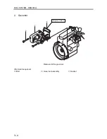
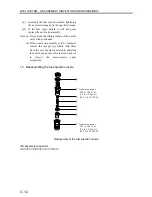
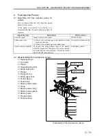
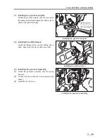
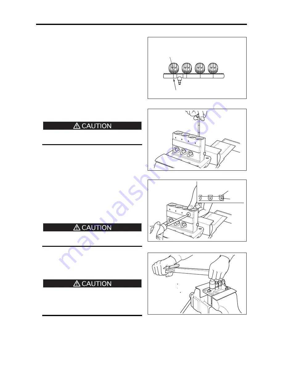
(3)
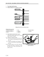
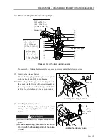
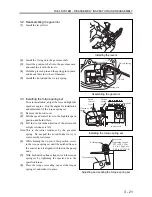
Installing the control sleeves
(a)
Assemble the control sleeves onto the control
rack so that each sleeve is aligned with the
notched line.
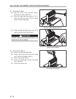
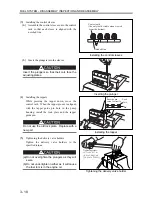
(b)
Insert the plungers into the sleeves.
Insert the plungers so that their cuts face the
adjusting plates.
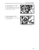
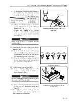
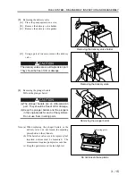
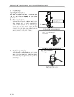
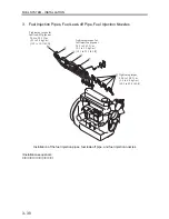
(4)
Installing
the
tappets
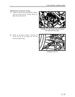
While pressing the tappet down, move the
control rack. When the tappet groove is aligned
with the tappet guide pin hole in the pump
housing, install the lock plate and the tappet
guide pin.
Do not use the old lock plate. Replace with a
new part.
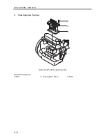
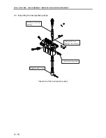
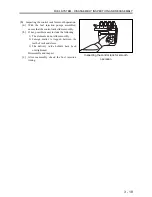
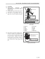
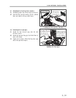
(5)
Tightening the delivery valve holders
Tighten the delivery valve holders to the
specified torque.
(a) Do not overtighten the plungers as they will
seize.
(b) Do not undertighten neither as it will cause
the fuel to mix in the engine oil.
Installing the control sleeves
Inserting the plunger
Installing the tappet
Tightening the delivery valve holder
Center tooth
(the only tooth visible when viewed
from the bottom)
Notched line
Face the pin
cutout correctly
Lock
plate
Pin
Tightening torque:
39.2 to 49.0 N m
(4.0 to 5.0 kgf m)
[28.9 to 36.2 lbf ft]
Summary of Contents for diesel engines
Page 5: ......
Page 33: ...SERVICE STANDARDS 1 20 ...
Page 34: ...1 General Tools 1 22 2 Special Tools 1 23 TOOLS LIST ...
Page 37: ...TOOLS LIST 1 24 ...
Page 41: ...OVERHAUL TIMING 1 28 ...
Page 46: ......
Page 47: ......
Page 61: ...ENGINE MAIN PARTS DISASSEMBLY 2 16 ...
Page 99: ...FUEL SYSTEM REMOVAL 3 8 ...
Page 115: ...FUEL SYSTEM DISASSEMBLY INSPECTION AND REASSEMBLY 3 24 ...
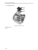
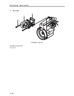
Page 119: ...FUEL SYSTEM INSTALLATION 3 28 2 Governor Installing the governor Installation sequence ...
Page 123: ...FUEL SYSTEM INSTALLATION 3 32 ...
Page 131: ...OIL SYSTEM DISASSEMBLY INSPECTION AND REASSEMBLY 4 8 ...
Page 143: ...COOLING SYSTEM DISASSEMBLY INSPECTION AND REASSEMBLY 5 8 ...
Page 150: ......
Page 151: ......
Page 153: ...INLET AND EXHAUST SYSTEMS REMOVAL 6 4 ...
Page 159: ...INLET AND EXHAUST SYSTEMS INSTALLATION 6 10 ...
Page 160: ...1 Starter 7 2 2 Alternator 7 3 3 Stop Solenoid 7 4 4 Glow Plug 7 5 ELECTRICAL SYSTEM REMOVAL ...
Page 165: ...ELECTRICAL SYSTEM REMOVAL 7 6 ...
Page 189: ...ELECTRICAL SYSTEM INSTALLATION 7 30 ...
Page 207: ...MISCELLANEOUS 9 4 ...


