ELECTRICAL SYSTEM - DISASSEMBLY, INSPECTION AND REASSEMBLY
7 - 23
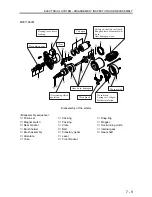
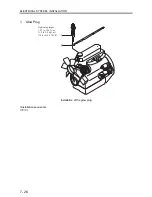
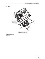
3. Stop
Solenoid
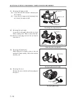
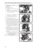
3.1 Reassembling the stop solenoid
Stop solenoid with rubber cap and plugs
(1)
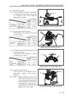
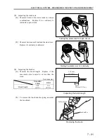
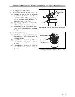
Apply sealant onto the threaded portion of the
stop solenoid.
Note: Apply sealant only to the area that will be
concealed by the governor case when installed.
Sealant ThreeBond
1212
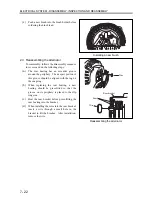
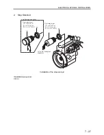
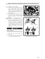
(2)
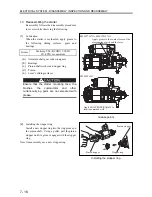
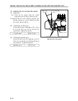
Loosely install the stop solenoid and the nut onto
the governor case.
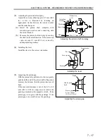
(3)
Move the fuel injection pump control rack fully
to the stop position.
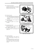
(4)
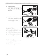
While pushing the plunger, screw in the stop
solenoid until the plunger contacts the control
rack. At this position the clearance A should be 0
mm (0 in.) (the position where the plunger is
screwed in along with the stop solenoid).
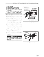
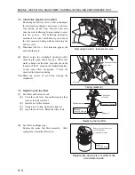
(5)
Back off the stop solenoid by 30° to 45° from the
position achieved in step (4) above until the
clearance between the rack and the plunger
becomes 0.15 to 0.20 mm (0.006 to 0.008 in.).
Tighten the nut to the specified torque.
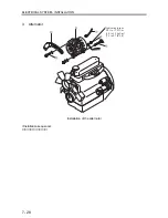
(6)
Start the engine. When the plunger is fully
pushed in, the engine should stop.
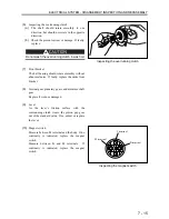
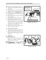
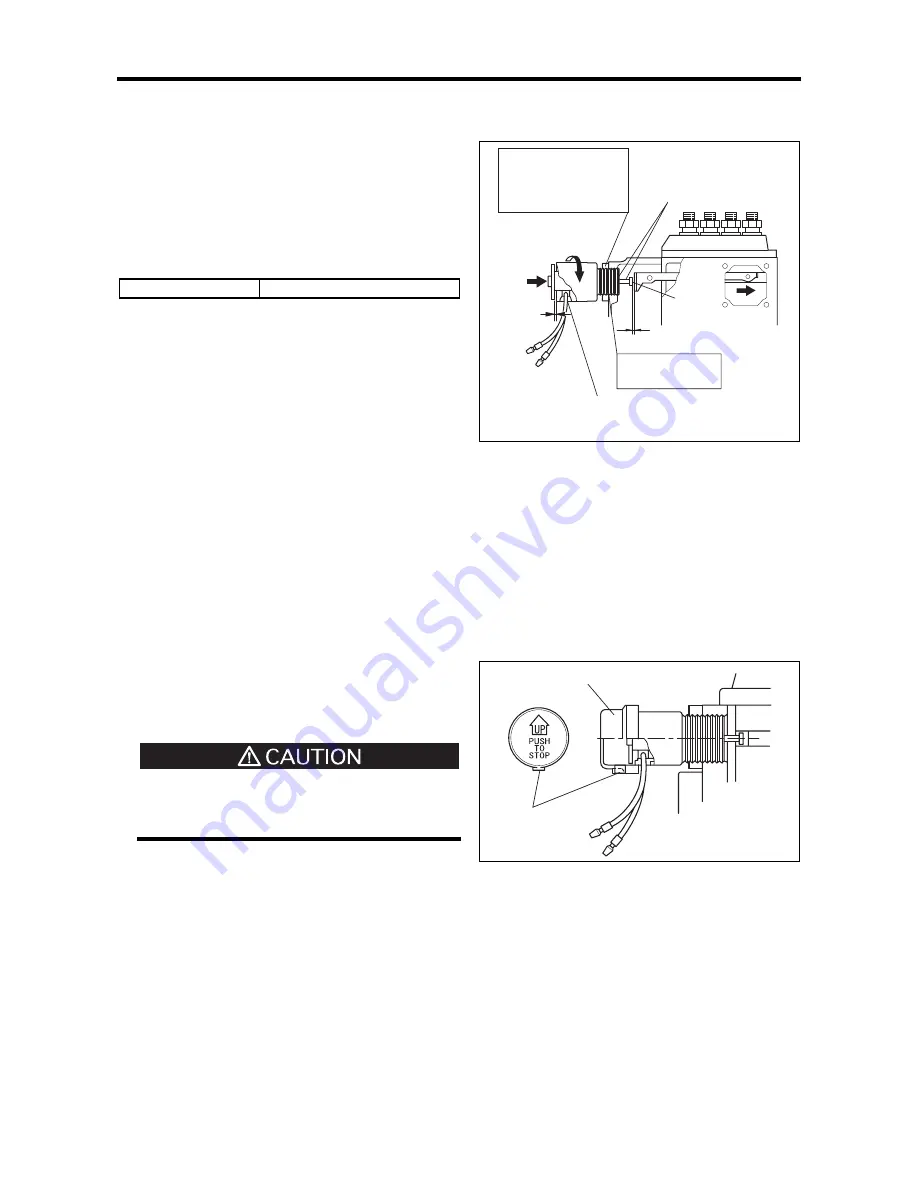
(7)
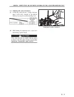
Install the rubber cap so that the arrow points
upwards (the water drain faces downwards) as
illustrated.
Ensure that the solenoid terminals and inner
parts (wiring and shaft) will not be exposed to
cleaning fluid.
Installing the stop solenoid
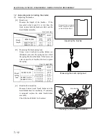
Installing the rubber cap
Rubber cap
Water drain
Threaded portion:
Apply sealant.
Shaft
These areas must be
free of sealant.
Tightening torque:
39.2 to 49.0 N
㨯
m
(4.0 to 5.0 kgf
㨯
m)
[28.9 to 36.2 lbf
㨯
ft]
There should be no intrusion/leak of cleaning
fluid through the gap into the solenoid
Clearance A
0.15 to 0.20 mm
(0.006 to 0.008 in.)
0 mm
(0 in.)
Summary of Contents for diesel engines
Page 5: ......
Page 33: ...SERVICE STANDARDS 1 20 ...
Page 34: ...1 General Tools 1 22 2 Special Tools 1 23 TOOLS LIST ...
Page 37: ...TOOLS LIST 1 24 ...
Page 41: ...OVERHAUL TIMING 1 28 ...
Page 46: ......
Page 47: ......
Page 61: ...ENGINE MAIN PARTS DISASSEMBLY 2 16 ...
Page 99: ...FUEL SYSTEM REMOVAL 3 8 ...
Page 115: ...FUEL SYSTEM DISASSEMBLY INSPECTION AND REASSEMBLY 3 24 ...
Page 119: ...FUEL SYSTEM INSTALLATION 3 28 2 Governor Installing the governor Installation sequence ...
Page 123: ...FUEL SYSTEM INSTALLATION 3 32 ...
Page 131: ...OIL SYSTEM DISASSEMBLY INSPECTION AND REASSEMBLY 4 8 ...
Page 143: ...COOLING SYSTEM DISASSEMBLY INSPECTION AND REASSEMBLY 5 8 ...
Page 150: ......
Page 151: ......
Page 153: ...INLET AND EXHAUST SYSTEMS REMOVAL 6 4 ...
Page 159: ...INLET AND EXHAUST SYSTEMS INSTALLATION 6 10 ...
Page 160: ...1 Starter 7 2 2 Alternator 7 3 3 Stop Solenoid 7 4 4 Glow Plug 7 5 ELECTRICAL SYSTEM REMOVAL ...
Page 165: ...ELECTRICAL SYSTEM REMOVAL 7 6 ...
Page 189: ...ELECTRICAL SYSTEM INSTALLATION 7 30 ...
Page 207: ...MISCELLANEOUS 9 4 ...


