
ENGINE - INSPECTION
/
ADJUSTMENT, RUNNING-IN TRIAL AND PERFORMANCE TEST
8 - 2
1. Inspection and Adjustment of Engine
1.1
Preparations for valve clearance
inspection and adjustment
(1)
Inspection and adjustment of valve clearance
should be performed when the engine is cold.
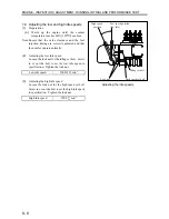
(2)
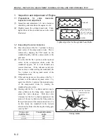
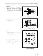
Slightly loosen the cylinder head bolts. Then,
tighten them to the specified torque in the order
illustrated.
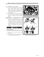
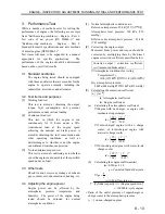
1.2 Inspecting the valve clearance
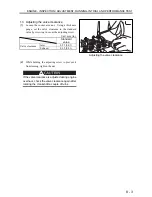
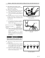
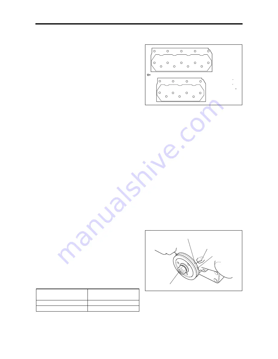
(1)
Move the piston of the No. 1 cylinder to the top
dead center of the compression stroke. This is
achieved by aligning the TDC mark on the
crankshaft pulley with the counter mark on the
gear case.
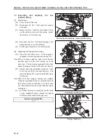
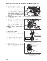
(2)
To verify that the No. 1 piston is at the top dead
center of the compression stroke, rotate the
crankshaft approx. 20º in both forward and
reverse directions. If the relevant rocker arm
does not move while rotating the crankshaft, the
No. 1 piston is at the top dead center of the
compression stroke.
(3)
If the rocker arm moves, the piston of the No. 1
cylinder is at the exhaust top dead center. Try
again to set the No. 1 piston at the top dead center
of the compression stroke by rotating the
crankshaft one more turn.
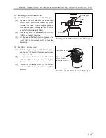
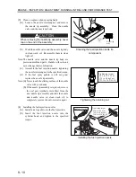
(4)
Starting with the No. 1 cylinder and moving to
other cylinders in the firing order, inspect and
adjust the valve clearance. With the valve
clearance for the No. 1 cylinder adjusted, set the
piston of the next cylinder in the firing order to
the top dead center of the compression stroke. To
do this, rotate the crankshaft in the forward
direction (clockwise when facing the timing gear
case) by 180º.
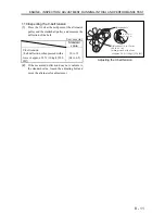
Firing order
(Cylinder No.)
Crankshaft rotation
angle
1-3-2 240º
1-3-4-2 180º
Tightening order for the cylinder head bolts
Timing marks
TDC mark for No. 1 and No. 4 pistons
Counter mark on
gear case
TDC mark for No. 2 and No. 3 pistons
IT mark
13
11
12
14
1
7
9
6
4
3
5
10
8
2
11
1
7
9
6
4
3
5
10
8
2
S4L,S4L2
S3L,S3L2
Front of engine
Tightening torque:
83.4 to 93.2 N m
(8.5 to 9.5 kgf m)
[61.5 to 68.7 lbf ft]
Summary of Contents for diesel engines
Page 5: ......
Page 33: ...SERVICE STANDARDS 1 20 ...
Page 34: ...1 General Tools 1 22 2 Special Tools 1 23 TOOLS LIST ...
Page 37: ...TOOLS LIST 1 24 ...
Page 41: ...OVERHAUL TIMING 1 28 ...
Page 46: ......
Page 47: ......
Page 61: ...ENGINE MAIN PARTS DISASSEMBLY 2 16 ...
Page 99: ...FUEL SYSTEM REMOVAL 3 8 ...
Page 115: ...FUEL SYSTEM DISASSEMBLY INSPECTION AND REASSEMBLY 3 24 ...
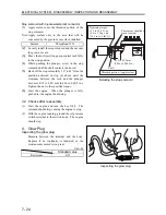
Page 119: ...FUEL SYSTEM INSTALLATION 3 28 2 Governor Installing the governor Installation sequence ...
Page 123: ...FUEL SYSTEM INSTALLATION 3 32 ...
Page 131: ...OIL SYSTEM DISASSEMBLY INSPECTION AND REASSEMBLY 4 8 ...
Page 143: ...COOLING SYSTEM DISASSEMBLY INSPECTION AND REASSEMBLY 5 8 ...
Page 150: ......
Page 151: ......
Page 153: ...INLET AND EXHAUST SYSTEMS REMOVAL 6 4 ...
Page 159: ...INLET AND EXHAUST SYSTEMS INSTALLATION 6 10 ...
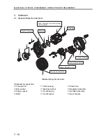
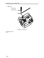
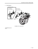
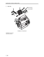
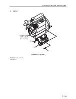
Page 160: ...1 Starter 7 2 2 Alternator 7 3 3 Stop Solenoid 7 4 4 Glow Plug 7 5 ELECTRICAL SYSTEM REMOVAL ...
Page 165: ...ELECTRICAL SYSTEM REMOVAL 7 6 ...
Page 189: ...ELECTRICAL SYSTEM INSTALLATION 7 30 ...
Page 207: ...MISCELLANEOUS 9 4 ...


