
ENGINE - INSPECTION
/
ADJUSTMENT, RUNNING-IN TRIAL AND PERFORMANCE TEST
8 - 4
1.4 Inspecting and adjusting the fuel
injection timing
(1)
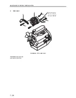
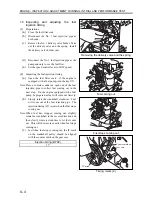
Preparations
(a)
Close the fuel filter cock.
(b)
Disconnect the No. 1 fuel injection pipe at
both ends.
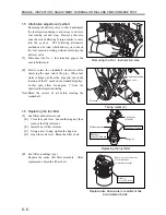
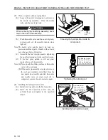
(c)
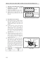
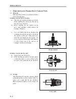
Remove the No. 1 delivery valve holder. Take
out the delivery valve and the spring. Install
the delivery valve holder only.
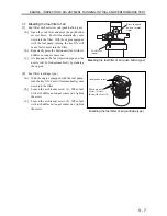
(d)
Reconnect the No. 1 fuel injection pipe at the
pump end only to see the fuel flow.
(e)
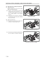
Set the speed control lever to LOW speed.
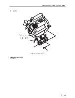
(2)
Inspecting the fuel injection timing
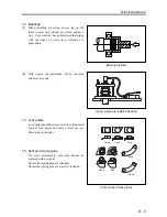
(a)
Open the fuel filter cock. If the engine is
equipped with a fuel pump, turn the key ON.
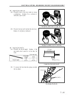
Note: Place a container under an open end of the fuel
injection pipe to collect fuel coming out in the
next step. On the engine equipped with a fuel
pump, be prepared as fuel will come out fiercely.
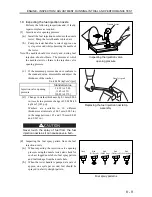
(b)
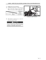
Slowly rotate the crankshaft clockwise. Fuel
will come out of the fuel injection pipe. The
injection timing (IT) is just when the fuel stops
coming out.
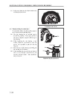
Note:
When fuel has stopped coming out, slightly
rotate the crankshaft in the reverse direction and
then slowly rotate it clockwise to let fuel come
out. This will show more exactly when fuel stops
coming out.
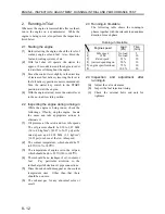
(c)
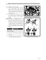
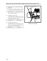
Just when fuel stops coming out, the IT mark
on the crankshaft pulley should be aligned
with the counter mark on the gear case.
Injection timing (BTDC)
17º
Removing the delivery valve and the spring
Fuel coming out
Fuel stops coming out
Timing marks (2)
Counter mark on
gear case
IT mark
Summary of Contents for diesel engines
Page 5: ......
Page 33: ...SERVICE STANDARDS 1 20 ...
Page 34: ...1 General Tools 1 22 2 Special Tools 1 23 TOOLS LIST ...
Page 37: ...TOOLS LIST 1 24 ...
Page 41: ...OVERHAUL TIMING 1 28 ...
Page 46: ......
Page 47: ......
Page 61: ...ENGINE MAIN PARTS DISASSEMBLY 2 16 ...
Page 99: ...FUEL SYSTEM REMOVAL 3 8 ...
Page 115: ...FUEL SYSTEM DISASSEMBLY INSPECTION AND REASSEMBLY 3 24 ...
Page 119: ...FUEL SYSTEM INSTALLATION 3 28 2 Governor Installing the governor Installation sequence ...
Page 123: ...FUEL SYSTEM INSTALLATION 3 32 ...
Page 131: ...OIL SYSTEM DISASSEMBLY INSPECTION AND REASSEMBLY 4 8 ...
Page 143: ...COOLING SYSTEM DISASSEMBLY INSPECTION AND REASSEMBLY 5 8 ...
Page 150: ......
Page 151: ......
Page 153: ...INLET AND EXHAUST SYSTEMS REMOVAL 6 4 ...
Page 159: ...INLET AND EXHAUST SYSTEMS INSTALLATION 6 10 ...
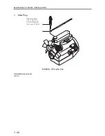
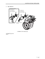
Page 160: ...1 Starter 7 2 2 Alternator 7 3 3 Stop Solenoid 7 4 4 Glow Plug 7 5 ELECTRICAL SYSTEM REMOVAL ...
Page 165: ...ELECTRICAL SYSTEM REMOVAL 7 6 ...
Page 189: ...ELECTRICAL SYSTEM INSTALLATION 7 30 ...
Page 207: ...MISCELLANEOUS 9 4 ...


