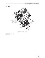


ENGINE - INSPECTION
/
ADJUSTMENT, RUNNING-IN TRIAL AND PERFORMANCE TEST
8 - 13
3. Performance
Test
While a number of methods exist for testing the
performance of engines, the following are excerpts
from “Earth-moving machinery - Engines - Part 1:
Test code of net power (JIS D0006-1)” and
“Earth-moving machinery - Engines - Part 2:
Standard format of specifications and tests methods
of diesel engines (JIS D0006-2).”
Test items will need to be expanded in a manner
appropriate for specific applications. The
performance of the engine should be determined
based on the overall test results.
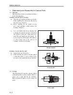
3.1 Standard ancillaries
The engine being tested should be equipped
with those ancillaries that are essential for the
engine to operate normally, including the
radiator fan, air cleaner, and alternator.
3.2 Test items and purposes
(1)
Working load test
This test is aimed at obtaining the output,
torque, fuel consumption, and governor
performance under various loading.
(2)
Continuous load test
This test, in which the engine is run
continuously for 10 hours under a 90%
(continuous) load at the engine speed
achieving the nominal net brake power, is
aimed at obtaining the fuel consumption and
other operating conditions, as well as
determining as to whether or not the engine
can withstand continuous operation.
(3)
No-load minimum speed test
This test is aimed at confirming as to whether
or not the engine can run stably at the specified
speed under no load.
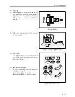
3.3 Other tests
Check for and correct any leakage of exhaust
gas, coolant or oil, abnormal odor, hunting, etc.
3.4 Adjusting the engine power
Engine power can be affected by the
atmospheric pressure, temperature and
humidity. The power of the engine being
tested should be adjusted for normal
atmospheric conditions.
(1)
Normal atmospheric conditions are:
Reference temperature: 298 K [25
℃
(77
°
F
)]
Atmospheric total pressure: 100 kPa (750
mmHg)
Reference dry atmospheric pressure : 99 kPa
(743 mmHg)
(2)
Correcting the engine output
Measured brake power and torque should be
corrected by multiplying them by the diesel
engine correction coefficient described below.
Corrected output = correction coefficient
(
α
c
)
×
measured brake output
・
Atmospheric conditions for testing
Temperature(T):
283 K [10
℃
(50
°
F
)]
≦
T
≦
313 K [40
℃
(104
°
F
)]
Dry atmospheric pressure:
80 kPa (600 mmHg)
≦
P
≦
110 kPa (825 mmHg)
(3)
Calculating the correction coefficient
α
c
=(
fa
)
fm
fa
: Atmospheric coefficient
fm
: Engine coefficient
(a)
Calculating the atmospheric coefficient
①
Engine with no charger, or engine with
mechanical supercharger
7
.
0
298
99
⋅
=
T
Pd
fa
②
Turbo-charged engine with no charge
cooler, or turbo-charged engine with
air-to-air charge cooler
2
.
1
298
99
⋅
=
T
Pd
fa
③
Turbo-charged engine with water-to-air
charge cooler
7
.
0
7
.
0
298
99
⋅
=
T
Pd
fa
(b) Calculating the engine coefficient(
fm
)
fm
=0.036
qc
-1.14
qc
: Corrected fuel delivery rate
①
r
q
qc
=
q
=
(
z
)
×
(Fuel flow rate
g/s
)
(Cylinder capacity
l
)
×
(Engine speed min
-1
)
z
=120000(4-cycle engine)
r
: Ratio of the outlet pressure of supercharger or
charge cooler to the atmospheric pressure
(
r
= 1 on non-charged engine)
Summary of Contents for diesel engines
Page 5: ......
Page 33: ...SERVICE STANDARDS 1 20 ...
Page 34: ...1 General Tools 1 22 2 Special Tools 1 23 TOOLS LIST ...
Page 37: ...TOOLS LIST 1 24 ...
Page 41: ...OVERHAUL TIMING 1 28 ...
Page 46: ......
Page 47: ......
Page 61: ...ENGINE MAIN PARTS DISASSEMBLY 2 16 ...
Page 99: ...FUEL SYSTEM REMOVAL 3 8 ...
Page 115: ...FUEL SYSTEM DISASSEMBLY INSPECTION AND REASSEMBLY 3 24 ...
Page 119: ...FUEL SYSTEM INSTALLATION 3 28 2 Governor Installing the governor Installation sequence ...
Page 123: ...FUEL SYSTEM INSTALLATION 3 32 ...
Page 131: ...OIL SYSTEM DISASSEMBLY INSPECTION AND REASSEMBLY 4 8 ...
Page 143: ...COOLING SYSTEM DISASSEMBLY INSPECTION AND REASSEMBLY 5 8 ...
Page 150: ......
Page 151: ......
Page 153: ...INLET AND EXHAUST SYSTEMS REMOVAL 6 4 ...
Page 159: ...INLET AND EXHAUST SYSTEMS INSTALLATION 6 10 ...
Page 160: ...1 Starter 7 2 2 Alternator 7 3 3 Stop Solenoid 7 4 4 Glow Plug 7 5 ELECTRICAL SYSTEM REMOVAL ...
Page 165: ...ELECTRICAL SYSTEM REMOVAL 7 6 ...
Page 189: ...ELECTRICAL SYSTEM INSTALLATION 7 30 ...
Page 207: ...MISCELLANEOUS 9 4 ...


