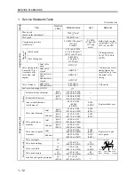
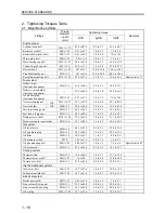


SERVICE STANDARDS
1 - 14
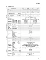
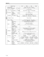
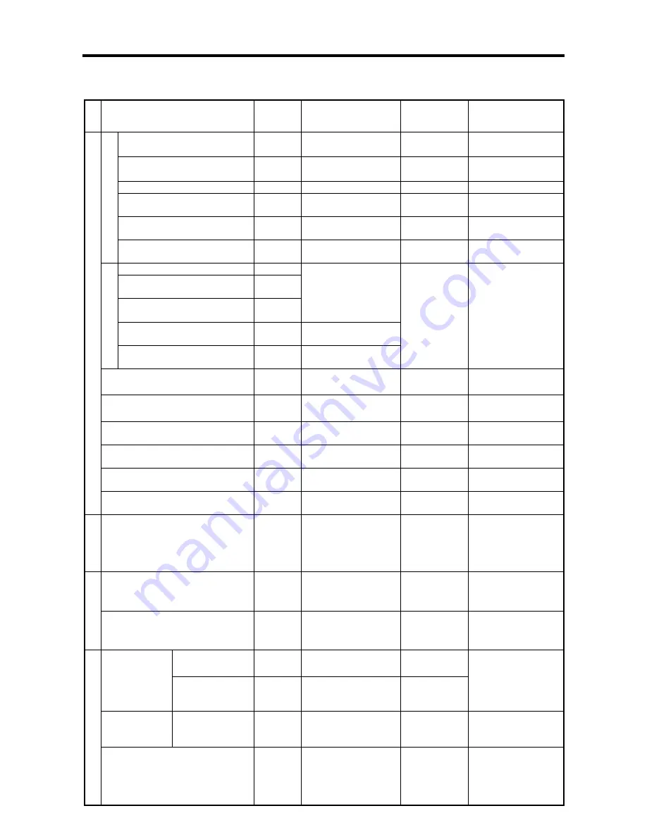
Unit: mm (in.)
Gro
up
Item
Nominal
value
Standard value
Limit
Remarks
Crank journal diameter (STD)
φ
52
(2.0488)
51.985 to 52.000
(2.0482 to 2.0488)
―
Crank pin diameter
φ
48
(1.8912)
47.950 to 47.964
(1.8892 to 1.8897)
―
Crankshaft bend
0.025 (0.0010)
0.050 (0.0020)
Correct or replace
Main bearings oil clearance
0.030 to 0.077
(0.0012 to 0.0030)
0.100
(0.0040)
Replace main
bearings
Connecting rod bearings oil
clearance
0.025 to 0.072
(0.0010 to 0.0028)
0.150
(0.0059)
Replace connecting
rod bearings
C
ran
ks
haft
End play
0.050 to 0.175
(0.0020 to 0.0069)
0.500
(0.0197)
Replace flanged No.
3 main bearings
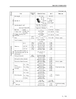
Crank gear to idler gear
Idler gear to valve camshaft
gear
Idler gear to pump camshaft
gear
0.040 to 0.120
(0.0015 to 0.0047)
Valve camshaft gear to PTO
gear
0.080 to 0.190
(0.0032 to 0.0075)
T
imi
ng gea
r ba
ckl
ash
Pump camshaft gear to oil
pump gear
0.070 to 0.200
(0.0028 to 0.0079)
0.300
(0.0120)
Replace
Camshaft cam height
(including lobe)
35.720
±
0.1
(1.4073
±
0.0394)
34.720
(1.3679)
Replace
Fuel injection pump shaft cam
height (including lobe)
44
±
0.1
(1.7336
±
0.0039)
43
(1.6942)
Replace
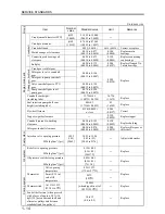
Flywheel flatness
0.150 (0.0059)
or less
0.500
(0.0197)
Correct
Tappet-to-guide clearance
―
0.150
(0.0059)
Replace tappet
Camshaft journal-to-bushing
clearance
0.050 to 0.125
(0.0020 to 0.0049)
0.150
(0.0059)
Replace bushing
Engine mai
n
p
a
rt
s
Idler gear-to-shaft clearance
0.020 to 0.070
(0.0008 to 0.0028)
0.200
(0.0079)
Replace idler gear or
idler shaft
Fuel system
Injection valve opening pressure
MPa (kgf/cm
2
) [psi]
14.22
(145)
[2062]
14.22 to 15.00
(145 to 153)
[2062 to 2176]
―
Adjust with washer
Relief valve opening pressure
MPa (kgf/cm
2
) [psi]
0.35
±
0.05
(3.5
±
0.5)
[50
±
7.2]
―
Replace
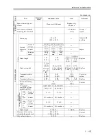
Oil sy
st
em
Oil pressure switch closing pressure
MPa (kgf/cm
2
) [psi]
0.05
±
0.01
(0.5
±
0.1)
[7
±
1.4]
―
Replace
Valve opening
temperature
82
±
1.5
℃
(179.6
±
2.7
°
F
)
―
Thermostat
8 mm (0.32 in.)
valve lift
temperature
95
℃
(203
°
F
)
―
Replace
Thermoswitch
At 111
±
3.5
℃
(231.8
±
6.3
°
F
)
30 M
Ω
[when dipped in oil of
105
℃
(221
°
F
)]
―
Replace
Cooli
ng syste
m
Fan belt deflection {when pressed
with a force of approx. 98 N (10
kgf) [22] between crankshaft and
alternator pulleys and between
crankshaft and fan pulleys}
10 to 12
(0.4 to 0.5)
―
Replace
Summary of Contents for diesel engines
Page 5: ......
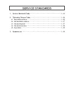
Page 33: ...SERVICE STANDARDS 1 20 ...
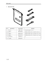
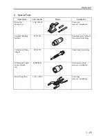
Page 34: ...1 General Tools 1 22 2 Special Tools 1 23 TOOLS LIST ...
Page 37: ...TOOLS LIST 1 24 ...
Page 41: ...OVERHAUL TIMING 1 28 ...
Page 46: ......
Page 47: ......
Page 61: ...ENGINE MAIN PARTS DISASSEMBLY 2 16 ...
Page 99: ...FUEL SYSTEM REMOVAL 3 8 ...
Page 115: ...FUEL SYSTEM DISASSEMBLY INSPECTION AND REASSEMBLY 3 24 ...
Page 119: ...FUEL SYSTEM INSTALLATION 3 28 2 Governor Installing the governor Installation sequence ...
Page 123: ...FUEL SYSTEM INSTALLATION 3 32 ...
Page 131: ...OIL SYSTEM DISASSEMBLY INSPECTION AND REASSEMBLY 4 8 ...
Page 143: ...COOLING SYSTEM DISASSEMBLY INSPECTION AND REASSEMBLY 5 8 ...
Page 150: ......
Page 151: ......
Page 153: ...INLET AND EXHAUST SYSTEMS REMOVAL 6 4 ...
Page 159: ...INLET AND EXHAUST SYSTEMS INSTALLATION 6 10 ...
Page 160: ...1 Starter 7 2 2 Alternator 7 3 3 Stop Solenoid 7 4 4 Glow Plug 7 5 ELECTRICAL SYSTEM REMOVAL ...
Page 165: ...ELECTRICAL SYSTEM REMOVAL 7 6 ...
Page 189: ...ELECTRICAL SYSTEM INSTALLATION 7 30 ...
Page 207: ...MISCELLANEOUS 9 4 ...


