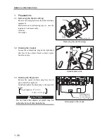


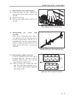
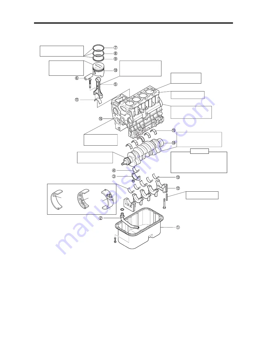
ENGINE MAIN PARTS - DISASSEMBLY
2 - 12
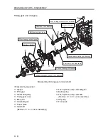
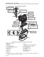
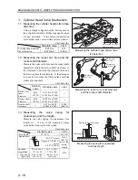
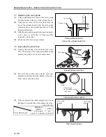
3. Cylinder
Block,
Crankshaft, Pistons, Oil Pan
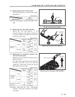
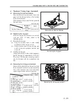
Cylinder damage,
stepped wear
Top face distortion
Connecting rod bend,
twist,
Big end thrust clearance
Crank journal/pin damage,
uneven wear, cracks, bend,
Clogged oil hole
The main bearings may be seized
due to poor oil maintenance etc.
In that case, the crankshaft must
be replaced.
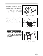
Caution
Damaged plugs and
knock pins
Dirty or clogged oil and
water galleries
Damaged crankshaft
gear teeth
Seizing
Scoring
Pealing
Piston ring wear, damage,
Ring gap clearance
Piston wear, seizure,
streak,
Ring groove wear
Replace: Side seal
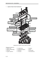
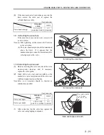
Disassembly of cylinder block, crankshaft, pistons and oil pan
<Disassembly sequence>
①
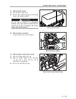
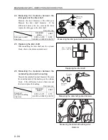
Oil pan
②
Oil strainer
③
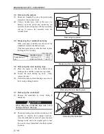
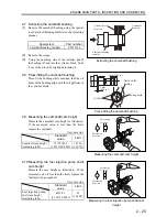
Connecting rod cap
④
Connecting rod bearing (lower)
⑤
Connecting rod
⑥
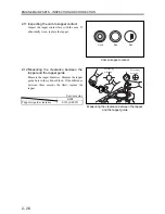
Piston pin
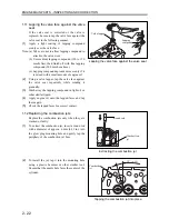
⑦
No. 1 ring
⑧
No. 2 ring
⑩
Piston
(Remove
⑤
to
⑩
as an assembly.)
⑪
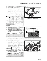
Connecting rod bearing (upper)
⑫
Main bearing cap
⑬
Main bearing (lower)
⑭
Crankshaft
⑮
Main bearing (upper)
⑯
Cylinder block
⑨
Oil ring
Note: If the crankcase is to be replaced, carefully remove the relief valve and other parts from the old
crankcase for reassembly onto the new crankcase.
Summary of Contents for diesel engines
Page 5: ......
Page 33: ...SERVICE STANDARDS 1 20 ...
Page 34: ...1 General Tools 1 22 2 Special Tools 1 23 TOOLS LIST ...
Page 37: ...TOOLS LIST 1 24 ...
Page 41: ...OVERHAUL TIMING 1 28 ...
Page 46: ......
Page 47: ......
Page 61: ...ENGINE MAIN PARTS DISASSEMBLY 2 16 ...
Page 99: ...FUEL SYSTEM REMOVAL 3 8 ...
Page 115: ...FUEL SYSTEM DISASSEMBLY INSPECTION AND REASSEMBLY 3 24 ...
Page 119: ...FUEL SYSTEM INSTALLATION 3 28 2 Governor Installing the governor Installation sequence ...
Page 123: ...FUEL SYSTEM INSTALLATION 3 32 ...
Page 131: ...OIL SYSTEM DISASSEMBLY INSPECTION AND REASSEMBLY 4 8 ...
Page 143: ...COOLING SYSTEM DISASSEMBLY INSPECTION AND REASSEMBLY 5 8 ...
Page 150: ......
Page 151: ......
Page 153: ...INLET AND EXHAUST SYSTEMS REMOVAL 6 4 ...
Page 159: ...INLET AND EXHAUST SYSTEMS INSTALLATION 6 10 ...
Page 160: ...1 Starter 7 2 2 Alternator 7 3 3 Stop Solenoid 7 4 4 Glow Plug 7 5 ELECTRICAL SYSTEM REMOVAL ...
Page 165: ...ELECTRICAL SYSTEM REMOVAL 7 6 ...
Page 189: ...ELECTRICAL SYSTEM INSTALLATION 7 30 ...
Page 207: ...MISCELLANEOUS 9 4 ...


