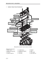


ENGINE MAIN PARTS - DISASSEMBLY
2 - 14
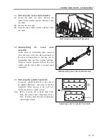
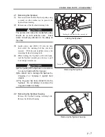
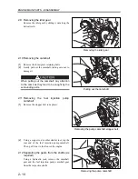
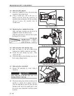
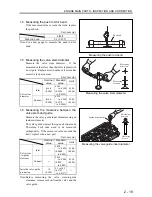
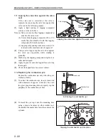
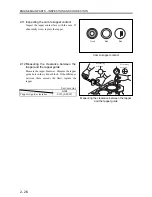
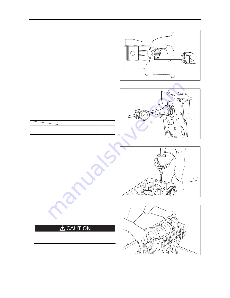
3.4 Removing the pistons
(1)
Rotate the crankshaft to place the piston being
removed at the top dead center.
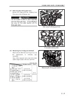
(2)
Using a wooden piece such as the stem of a
hammer, push the piston and connecting rod
assembly on the mating face with the connecting
rod cap to remove the assembly from the
cylinder block.
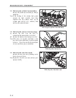
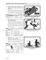
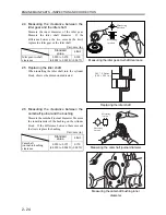
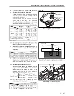
3.5 Measuring the crankshaft end play
With a dial gauge installed onto the end of the
crankshaft, measure the shaft end play.
If the measured value exceeds the limit, replace
the flanged No. 3 bearing.
Unit: mm (in.)
Standard
value
Limit
Crankshaft end
play
0.050 to 0.175
(0.0020 to 0.0069)
0.500
(0.0197)
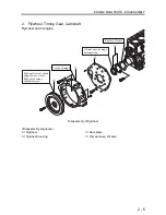
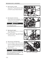
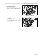
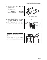
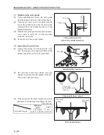
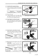
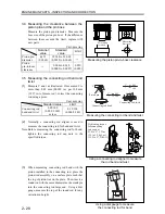
3.6 Removing the main bearing caps
(1)
Place the engine so that the cylinder block
mating surface with the oil pan faces upwards.
(2)
Loosen the main bearing cap bolts. Then,
remove the caps.
(3)
On the front and rear main bearing caps, remove
these using a sliding hammer.
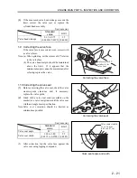
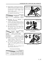
3.7 Removing the crankshaft
(1)
Remove the crankshaft by slowly lifting it
straight up.
When lifting the crankshaft, take care not to
damage the main bearings.
(2)
The main bearings may fall down, making it not
possible to identify their original locations.
Once the crankshaft is removed, place the main
bearings neatly and in the original pairs so that
they can be reassembled back onto their original
locations.
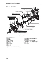
Removing the piston
Measuring the crankshaft end play
Removing the main bearing cap
Removing the crankshaft
Summary of Contents for diesel engines
Page 5: ......
Page 33: ...SERVICE STANDARDS 1 20 ...
Page 34: ...1 General Tools 1 22 2 Special Tools 1 23 TOOLS LIST ...
Page 37: ...TOOLS LIST 1 24 ...
Page 41: ...OVERHAUL TIMING 1 28 ...
Page 46: ......
Page 47: ......
Page 61: ...ENGINE MAIN PARTS DISASSEMBLY 2 16 ...
Page 99: ...FUEL SYSTEM REMOVAL 3 8 ...
Page 115: ...FUEL SYSTEM DISASSEMBLY INSPECTION AND REASSEMBLY 3 24 ...
Page 119: ...FUEL SYSTEM INSTALLATION 3 28 2 Governor Installing the governor Installation sequence ...
Page 123: ...FUEL SYSTEM INSTALLATION 3 32 ...
Page 131: ...OIL SYSTEM DISASSEMBLY INSPECTION AND REASSEMBLY 4 8 ...
Page 143: ...COOLING SYSTEM DISASSEMBLY INSPECTION AND REASSEMBLY 5 8 ...
Page 150: ......
Page 151: ......
Page 153: ...INLET AND EXHAUST SYSTEMS REMOVAL 6 4 ...
Page 159: ...INLET AND EXHAUST SYSTEMS INSTALLATION 6 10 ...
Page 160: ...1 Starter 7 2 2 Alternator 7 3 3 Stop Solenoid 7 4 4 Glow Plug 7 5 ELECTRICAL SYSTEM REMOVAL ...
Page 165: ...ELECTRICAL SYSTEM REMOVAL 7 6 ...
Page 189: ...ELECTRICAL SYSTEM INSTALLATION 7 30 ...
Page 207: ...MISCELLANEOUS 9 4 ...


