
ENGINE MAIN PARTS - INSPECTION AND CORRECTION
2 - 20
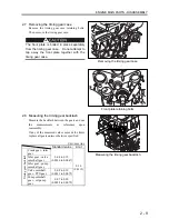
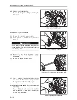
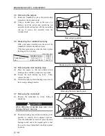
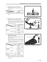
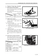
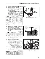
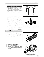
1.7 Replacing the valve guide
(1)
Using a punching tool, remove the valve guide
from the bottom to the top of the cylinder head.
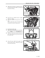
(2)
Using a press, insert a new valve guide from the
top of the cylinder head so that the valve guide
protrusion above the cylinder head face is to the
indicated dimension.
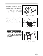
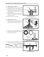
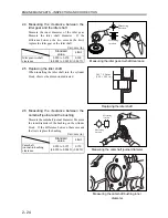
(3)
With the valve guide press-fit into position, insert
a new valve to verify that it slides smoothly
inside the valve guide.
(4)
Check the valve face-to-seat contact.
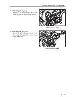
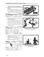
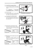
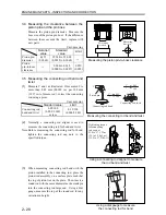
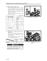
1.8 Inspecting the valve face
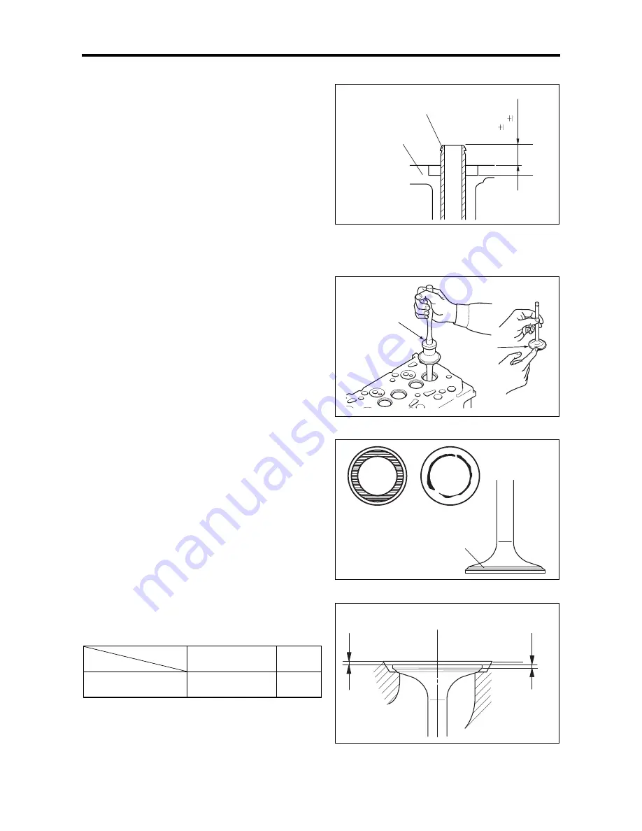
(1)
Apply a thin coating of red lead onto the valve
face. Then, using a valve lapper (available on the
market), check the valve face-to-seat contact.
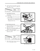
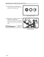
(2)
The valve face contact area with the valve seat
should be uniform and in the middle of the face.
If not, reface with valve facer.
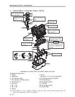
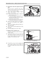
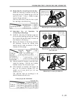
(3)
If the measured valve head margin (valve head
thickness) is less than the limit, replace the valve.
Unit: mm (in.)
Standard
value
Limit
Valve head margin
1.35 to 0.65
(0.0531 to 0.0650)
0.5
(0.0197)
Valve guide protrusion
above the cylinder head face
Inspecting the valve face
Valve seat-to-face contact
Valve head sinkage
Red lead
Valve lapper
Valve head
sinkage
Valve head
margin
Valve guide
Cylinder head
10
0.5 mm
(0.39
0.20 in.)
[15 mm]
(0.59 in.)
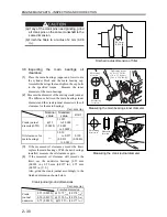
Good
Bad
Contact area
(in the middle of the
valve face)
Summary of Contents for diesel engines
Page 5: ......
Page 33: ...SERVICE STANDARDS 1 20 ...
Page 34: ...1 General Tools 1 22 2 Special Tools 1 23 TOOLS LIST ...
Page 37: ...TOOLS LIST 1 24 ...
Page 41: ...OVERHAUL TIMING 1 28 ...
Page 46: ......
Page 47: ......
Page 61: ...ENGINE MAIN PARTS DISASSEMBLY 2 16 ...
Page 99: ...FUEL SYSTEM REMOVAL 3 8 ...
Page 115: ...FUEL SYSTEM DISASSEMBLY INSPECTION AND REASSEMBLY 3 24 ...
Page 119: ...FUEL SYSTEM INSTALLATION 3 28 2 Governor Installing the governor Installation sequence ...
Page 123: ...FUEL SYSTEM INSTALLATION 3 32 ...
Page 131: ...OIL SYSTEM DISASSEMBLY INSPECTION AND REASSEMBLY 4 8 ...
Page 143: ...COOLING SYSTEM DISASSEMBLY INSPECTION AND REASSEMBLY 5 8 ...
Page 150: ......
Page 151: ......
Page 153: ...INLET AND EXHAUST SYSTEMS REMOVAL 6 4 ...
Page 159: ...INLET AND EXHAUST SYSTEMS INSTALLATION 6 10 ...
Page 160: ...1 Starter 7 2 2 Alternator 7 3 3 Stop Solenoid 7 4 4 Glow Plug 7 5 ELECTRICAL SYSTEM REMOVAL ...
Page 165: ...ELECTRICAL SYSTEM REMOVAL 7 6 ...
Page 189: ...ELECTRICAL SYSTEM INSTALLATION 7 30 ...
Page 207: ...MISCELLANEOUS 9 4 ...


