ENGINE MAIN PARTS - INSPECTION AND CORRECTION
2 - 25
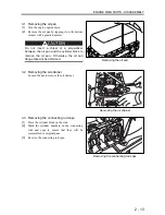
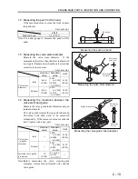
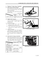
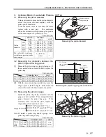
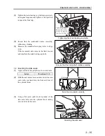
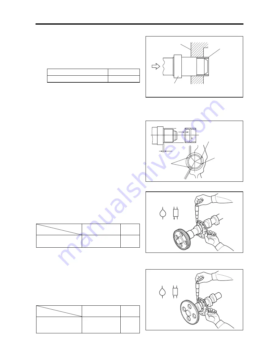
2.7 Extracting the camshaft bushing
(1)
Remove the camshaft bushing using the special
tool Camshaft Bushing Installer in the following
manner.
Special tool
Part number
Camshaft Bushing Installer
ST332340
(2)
Remove the oil pan.
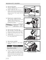
(3)
Using the punching side of the installer, punch
the bushing off and into the cylinder block. Take
it out of the block by slightly deforming it.
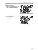
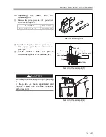
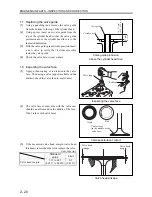
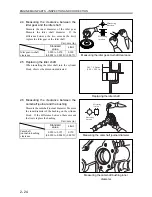
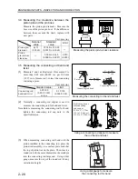
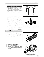
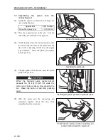
2.8 Press-fitting the camshaft bushing
Press-fit the bushing while ensuring that the oil
holes of the bushing align with the oil galleries in
the cylinder block.
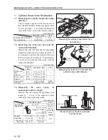
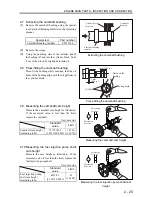
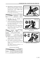
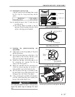
2.9 Measuring the camshaft cam height
Measure the camshaft cam height as illustrated.
If the measured value is less than the limit,
replace the camshaft.
Unit: mm (in.)
Standard
value
Limit
Camshaft cam height
(including lobe)
35.720
±
0.1
(1.4073
±
0.0039)
34.720
(1.3679)
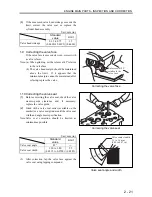
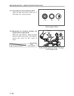
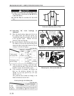
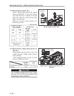
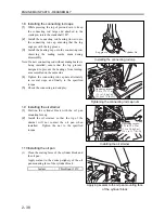
2.10 Measuring the fuel injection pump shaft
cam height
Measure the cam height as illustrated. If the
measured value is less than the limit, replace the
fuel injection pump shaft.
Unit: mm (in.)
Standard
value
Limit
Fuel injection pump
shaft cam height
(including lobe)
44
±
0.1
(1.736
±
0.0039)
43
(1.6942)
Extracting the camshaft bushing
Press-fitting the camshaft bushing
Measuring the camshaft cam height
Measuring the fuel injection pump shaft cam
height
Measuring
location
Measuring
direction
Measuring
location
Measuring
direction
Cylinder block
front face
Camshaft
bushing
Camshaft bushing
installer
1 mm (0.04 in.)
1 mm
(0.04 in.)
Oil hole
Notch on the
bushing
Mating mark
Summary of Contents for diesel engines
Page 5: ......
Page 33: ...SERVICE STANDARDS 1 20 ...
Page 34: ...1 General Tools 1 22 2 Special Tools 1 23 TOOLS LIST ...
Page 37: ...TOOLS LIST 1 24 ...
Page 41: ...OVERHAUL TIMING 1 28 ...
Page 46: ......
Page 47: ......
Page 61: ...ENGINE MAIN PARTS DISASSEMBLY 2 16 ...
Page 99: ...FUEL SYSTEM REMOVAL 3 8 ...
Page 115: ...FUEL SYSTEM DISASSEMBLY INSPECTION AND REASSEMBLY 3 24 ...
Page 119: ...FUEL SYSTEM INSTALLATION 3 28 2 Governor Installing the governor Installation sequence ...
Page 123: ...FUEL SYSTEM INSTALLATION 3 32 ...
Page 131: ...OIL SYSTEM DISASSEMBLY INSPECTION AND REASSEMBLY 4 8 ...
Page 143: ...COOLING SYSTEM DISASSEMBLY INSPECTION AND REASSEMBLY 5 8 ...
Page 150: ......
Page 151: ......
Page 153: ...INLET AND EXHAUST SYSTEMS REMOVAL 6 4 ...
Page 159: ...INLET AND EXHAUST SYSTEMS INSTALLATION 6 10 ...
Page 160: ...1 Starter 7 2 2 Alternator 7 3 3 Stop Solenoid 7 4 4 Glow Plug 7 5 ELECTRICAL SYSTEM REMOVAL ...
Page 165: ...ELECTRICAL SYSTEM REMOVAL 7 6 ...
Page 189: ...ELECTRICAL SYSTEM INSTALLATION 7 30 ...
Page 207: ...MISCELLANEOUS 9 4 ...


