ENGINE MAIN PARTS - INSPECTION AND CORRECTION
2 - 30
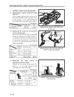
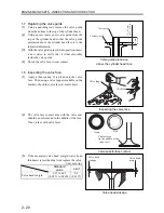
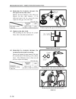
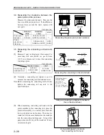
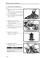
(a) If any of the crank pins need grinding, grind
all crank pins on the same crankshaft to the
same dimension.
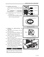
(b) Finish the fillets to a radius of 2 mm (0.08
in.).
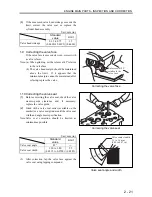
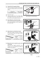
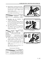
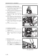
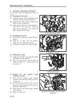
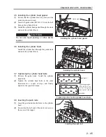
3.8
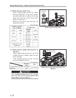
Inspecting the main bearings oil
clearance
(1)
Place the main bearings (upper and lower) onto
the cylinder block and the main bearing cap.
Assemble them together and tighten the cap bolts
to the specified torque. Measure the inner
diameter of the main bearings.
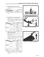
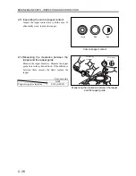
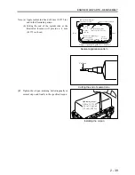
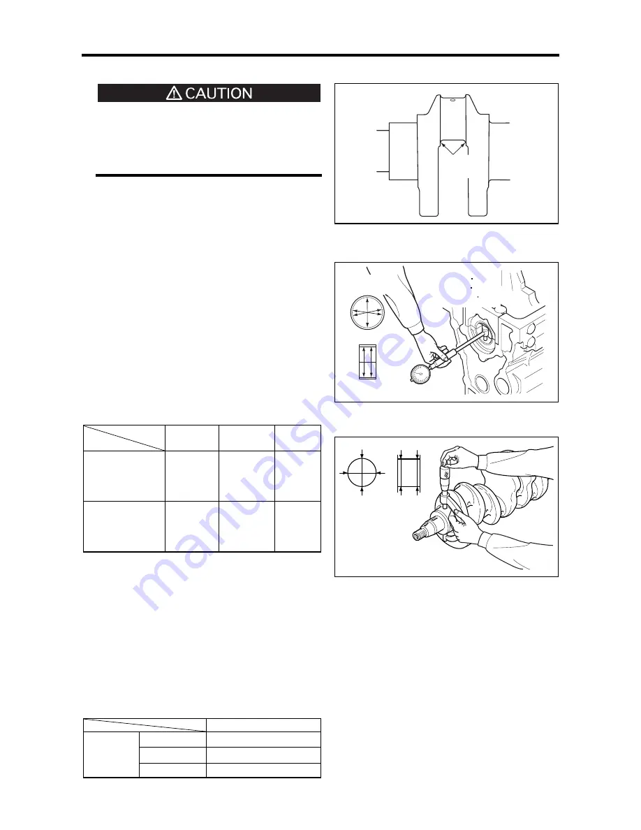
(2)
Measure the diameter of the mating crank journal.
The difference between the main bearings inner
diameter and the crank journal diameter is the oil
clearance for the main bearings.
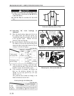
Unit: mm (in.)
Nominal
value
Standard
value
Limit
Crank journal
diameter(STD)
φ
52
(2.0488)
51.985
to 52.000
(2.0482
to 2.0488)
―
Oil clearance for
main bearings
―
0.030
to 0.077
(0.0012
to 0.003)
0.100
(0.0040)
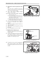
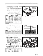
(3)
If the measured oil clearance exceeds the limit,
replace the main bearings. With the new bearings
installed, measure the oil clearance again.
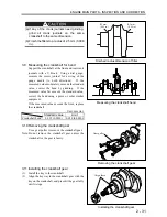
(4)
If the measured oil clearance still exceeds the
limit, use the undersize bearings [0.25 mm
(0.0098 in.), 0.50 mm (0.0197 in.), 0.75 mm
(0.0295 in.) U.S.]
Also, grind the crank journal accordingly to the
finished dimension shown below.
Crank journal ground dimensions
Unit: mm (in.)
Finished dimension
0.25 (0.0098)
φ
51.75
0
-0.015
(2.0374
0
-0.006
)
0.50 (0.0197)
φ
51.50
0
-0.015
(2.0276
0
-0.006
)
Crank
journal
undersize
0.75 (0.0295)
φ
51.25
0
-0.015
(2.0177
0
-0.006
)
Finished radius dimension of fillet
Measuring the main bearings inner diameter
Measuring the crank journal diameter
Measuring
location
Measuring
direction
R2.5 mm
(0.098 in.)
Measuring
location
Measuring
direction
Tightening torque
49.0 to 53.9 N m
(5.0 to 5.5 kgf m)
[36.2 to 39.8 lbf ft]
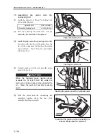
Summary of Contents for diesel engines
Page 5: ......
Page 33: ...SERVICE STANDARDS 1 20 ...
Page 34: ...1 General Tools 1 22 2 Special Tools 1 23 TOOLS LIST ...
Page 37: ...TOOLS LIST 1 24 ...
Page 41: ...OVERHAUL TIMING 1 28 ...
Page 46: ......
Page 47: ......
Page 61: ...ENGINE MAIN PARTS DISASSEMBLY 2 16 ...
Page 99: ...FUEL SYSTEM REMOVAL 3 8 ...
Page 115: ...FUEL SYSTEM DISASSEMBLY INSPECTION AND REASSEMBLY 3 24 ...
Page 119: ...FUEL SYSTEM INSTALLATION 3 28 2 Governor Installing the governor Installation sequence ...
Page 123: ...FUEL SYSTEM INSTALLATION 3 32 ...
Page 131: ...OIL SYSTEM DISASSEMBLY INSPECTION AND REASSEMBLY 4 8 ...
Page 143: ...COOLING SYSTEM DISASSEMBLY INSPECTION AND REASSEMBLY 5 8 ...
Page 150: ......
Page 151: ......
Page 153: ...INLET AND EXHAUST SYSTEMS REMOVAL 6 4 ...
Page 159: ...INLET AND EXHAUST SYSTEMS INSTALLATION 6 10 ...
Page 160: ...1 Starter 7 2 2 Alternator 7 3 3 Stop Solenoid 7 4 4 Glow Plug 7 5 ELECTRICAL SYSTEM REMOVAL ...
Page 165: ...ELECTRICAL SYSTEM REMOVAL 7 6 ...
Page 189: ...ELECTRICAL SYSTEM INSTALLATION 7 30 ...
Page 207: ...MISCELLANEOUS 9 4 ...


