ENGINE MAIN PARTS - REASSEMBLY
2 - 37
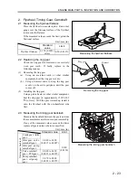
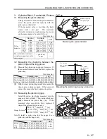
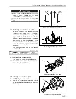
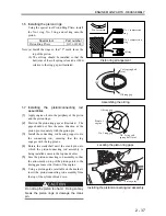
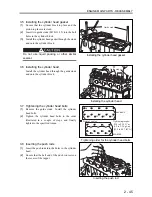
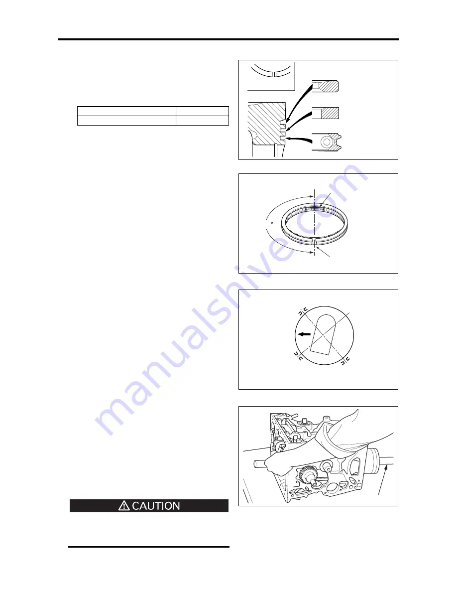
1.6 Installing the piston rings
Using the special tool Piston Ring Pliers, install
the No. 1 ring, No. 2 ring, and oil ring onto the
piston.
Special tool
Part number
Piston Ring Pliers
31391-12900
Note: (a) Install the rings so that “T” mark faces the
top of the piston.
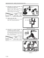
(b) The oil ring should be installed so that the
butt joint of the coil spring is located at 180
o
relative to the ring gap as illustrated.
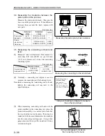
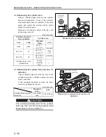
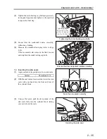
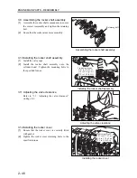
1.7 Installing the piston/connecting rod
assemblies
(1)
Apply engine oil onto the periphery of the piston
and the piston rings.
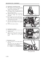
(2)
Position the piston ring gaps as illustrated. The
gaps should not face the same direction as the
piston pin or squarely with the piston pin
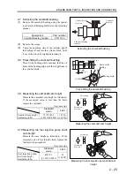
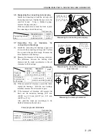
(3)
Install the connecting rod bearing (upper) onto
the connecting rod, ensuring that the lug
engages with the lug groove.
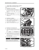
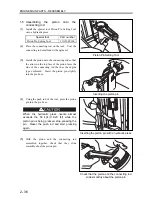
(4)
Rotate the crankshaft until the crank pin onto
which the piston/connecting rod assembly is
being installed comes to the top dead center.
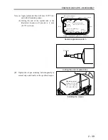
(5)
Face the piston/connecting rod assembly so that
the arrow mark on top of the piston points to the
timing gear case side (front) of the engine.
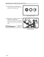
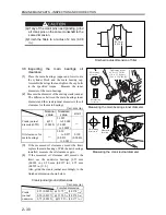
(6)
Using a piston guide (available on the market),
insert the piston/connecting rod assembly from
the top of the cylinder block down.
Do not tap the piston too hard. Doing so may
break the piston rings or damage the crank
pin.
Piston ring arrangement
Assembling the oil ring
Locating the piston ring gaps
Installing the piston/connecting rod assembly
Top face mark
No. 1 compression
ring
No. 2 compression
ring
Oil ring
Oil ring gap
Coil spring butt
joint
180
No. 2 ring coil
spring butt joint
No. 1 ring gap
Oil ring gap
Front of
engine
Piston guide
Summary of Contents for diesel engines
Page 5: ......
Page 33: ...SERVICE STANDARDS 1 20 ...
Page 34: ...1 General Tools 1 22 2 Special Tools 1 23 TOOLS LIST ...
Page 37: ...TOOLS LIST 1 24 ...
Page 41: ...OVERHAUL TIMING 1 28 ...
Page 46: ......
Page 47: ......
Page 61: ...ENGINE MAIN PARTS DISASSEMBLY 2 16 ...
Page 99: ...FUEL SYSTEM REMOVAL 3 8 ...
Page 115: ...FUEL SYSTEM DISASSEMBLY INSPECTION AND REASSEMBLY 3 24 ...
Page 119: ...FUEL SYSTEM INSTALLATION 3 28 2 Governor Installing the governor Installation sequence ...
Page 123: ...FUEL SYSTEM INSTALLATION 3 32 ...
Page 131: ...OIL SYSTEM DISASSEMBLY INSPECTION AND REASSEMBLY 4 8 ...
Page 143: ...COOLING SYSTEM DISASSEMBLY INSPECTION AND REASSEMBLY 5 8 ...
Page 150: ......
Page 151: ......
Page 153: ...INLET AND EXHAUST SYSTEMS REMOVAL 6 4 ...
Page 159: ...INLET AND EXHAUST SYSTEMS INSTALLATION 6 10 ...
Page 160: ...1 Starter 7 2 2 Alternator 7 3 3 Stop Solenoid 7 4 4 Glow Plug 7 5 ELECTRICAL SYSTEM REMOVAL ...
Page 165: ...ELECTRICAL SYSTEM REMOVAL 7 6 ...
Page 189: ...ELECTRICAL SYSTEM INSTALLATION 7 30 ...
Page 207: ...MISCELLANEOUS 9 4 ...


