
ENGINE MAIN PARTS - REASSEMBLY
2 - 39
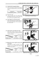
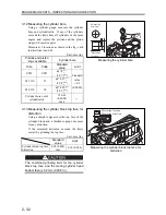
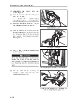
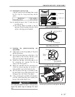
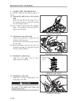
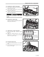
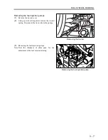
Note: (a) Apply sealant in a bead of 4 mm (0.1575 in.)
and in the illustrated pattern.
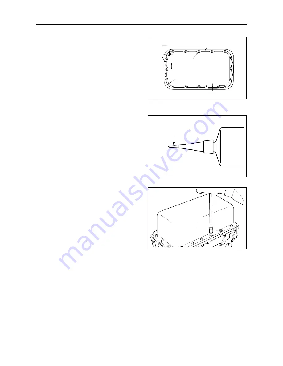
(b) Cutting the end of the sealant tube at the
illustrated location will provide a 4 mm
(0.1575 in.) bead.
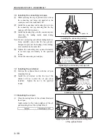
(2)
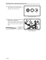
Tighten the oil pan retaining bolts diagonally in
several steps, and finally to the specified torque.
Sealant application pattern
Cutting the end of sealant tube
Installing the oil pan
Cut here
Tightening torque:
9.80 to 12.7 N m
(1.0 to 1.3 kgf m)
[7.2 to 9.4 lbf ft]
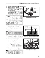
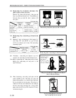
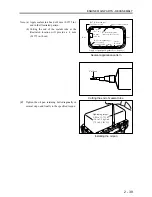
R17 (4 front and rear
locations in total)
Apply sealant as lined
9.5 mm
(0.37 in.)
R7 from hole center
(same for all 17 holes)
36 mm
(1.42 in.)
Rear
Front
R40 corresponding to
hole centers
(same for all 4 corners)
5 mm
(0.20 in.)
Apply oil pan liquid gasket here (top face)
Summary of Contents for diesel engines
Page 5: ......
Page 33: ...SERVICE STANDARDS 1 20 ...
Page 34: ...1 General Tools 1 22 2 Special Tools 1 23 TOOLS LIST ...
Page 37: ...TOOLS LIST 1 24 ...
Page 41: ...OVERHAUL TIMING 1 28 ...
Page 46: ......
Page 47: ......
Page 61: ...ENGINE MAIN PARTS DISASSEMBLY 2 16 ...
Page 99: ...FUEL SYSTEM REMOVAL 3 8 ...
Page 115: ...FUEL SYSTEM DISASSEMBLY INSPECTION AND REASSEMBLY 3 24 ...
Page 119: ...FUEL SYSTEM INSTALLATION 3 28 2 Governor Installing the governor Installation sequence ...
Page 123: ...FUEL SYSTEM INSTALLATION 3 32 ...
Page 131: ...OIL SYSTEM DISASSEMBLY INSPECTION AND REASSEMBLY 4 8 ...
Page 143: ...COOLING SYSTEM DISASSEMBLY INSPECTION AND REASSEMBLY 5 8 ...
Page 150: ......
Page 151: ......
Page 153: ...INLET AND EXHAUST SYSTEMS REMOVAL 6 4 ...
Page 159: ...INLET AND EXHAUST SYSTEMS INSTALLATION 6 10 ...
Page 160: ...1 Starter 7 2 2 Alternator 7 3 3 Stop Solenoid 7 4 4 Glow Plug 7 5 ELECTRICAL SYSTEM REMOVAL ...
Page 165: ...ELECTRICAL SYSTEM REMOVAL 7 6 ...
Page 189: ...ELECTRICAL SYSTEM INSTALLATION 7 30 ...
Page 207: ...MISCELLANEOUS 9 4 ...


