
ENGINE MAIN PARTS - REASSEMBLY
2 - 41
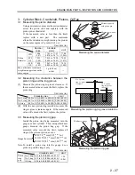
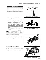
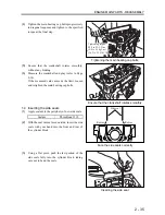
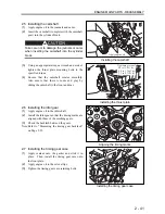
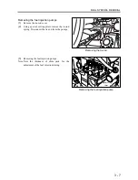
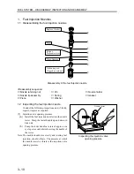
2.5 Installing the camshaft
(1)
Apply engine oil to the journals and cams.
(2)
Insert the camshaft (complete with the camshaft
gear) into the cylinder block.
Take care not to damage the journals or cams
when inserting the camshaft into the cylinder
block.
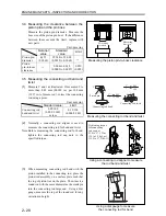
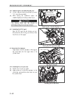
(3)
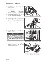
Using an appropriate torque wrench and socket,
tighten the thrust plate mounting bolts to the
specified torque.
(4)
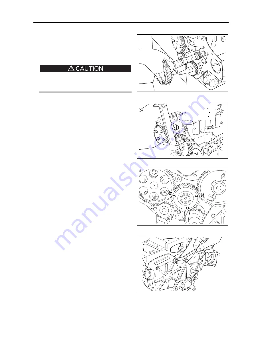
Ensure that the camshaft rotates smoothly.
Also ensure that there is some end play by
sliding the camshaft to the front and rear.
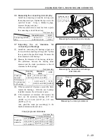
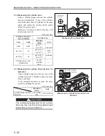
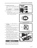
2.6 Installing the idler gear
(1)
Apply engine oil to the idler shaft.
(2)
Install the idler gear so that the timing marks are
aligned with those of the meshing gears.
(3)
Check the backlash between the gears.
Note: Refer to “Measuring the timing gear backlash”
on Page 2-23.
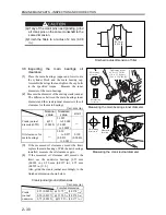
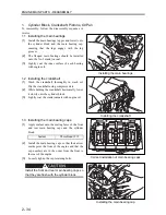
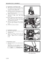
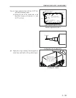
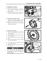
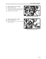
2.7 Installing the timing gear case
(1)
Apply sealant onto the gasket and stick it in
place. Then, install the timing gear case onto
the front plate.
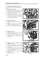
(2)
Apply engine oil to the oil seal lips.
(3)
Tighten the timing gear case retaining bolts.
Installing the camshaft
Installing the thrust plate
Aligning the timing marks
Installing the timing gear case
Apply engine oil
Tightening torque:
9.8 to 11.8 N m
(1.0 to 1.2 kgf m)
[7.2 to 8.7 lbf ft]
Summary of Contents for diesel engines
Page 5: ......
Page 33: ...SERVICE STANDARDS 1 20 ...
Page 34: ...1 General Tools 1 22 2 Special Tools 1 23 TOOLS LIST ...
Page 37: ...TOOLS LIST 1 24 ...
Page 41: ...OVERHAUL TIMING 1 28 ...
Page 46: ......
Page 47: ......
Page 61: ...ENGINE MAIN PARTS DISASSEMBLY 2 16 ...
Page 99: ...FUEL SYSTEM REMOVAL 3 8 ...
Page 115: ...FUEL SYSTEM DISASSEMBLY INSPECTION AND REASSEMBLY 3 24 ...
Page 119: ...FUEL SYSTEM INSTALLATION 3 28 2 Governor Installing the governor Installation sequence ...
Page 123: ...FUEL SYSTEM INSTALLATION 3 32 ...
Page 131: ...OIL SYSTEM DISASSEMBLY INSPECTION AND REASSEMBLY 4 8 ...
Page 143: ...COOLING SYSTEM DISASSEMBLY INSPECTION AND REASSEMBLY 5 8 ...
Page 150: ......
Page 151: ......
Page 153: ...INLET AND EXHAUST SYSTEMS REMOVAL 6 4 ...
Page 159: ...INLET AND EXHAUST SYSTEMS INSTALLATION 6 10 ...
Page 160: ...1 Starter 7 2 2 Alternator 7 3 3 Stop Solenoid 7 4 4 Glow Plug 7 5 ELECTRICAL SYSTEM REMOVAL ...
Page 165: ...ELECTRICAL SYSTEM REMOVAL 7 6 ...
Page 189: ...ELECTRICAL SYSTEM INSTALLATION 7 30 ...
Page 207: ...MISCELLANEOUS 9 4 ...


