ENGINE MAIN PARTS - REASSEMBLY
2 - 43
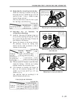
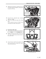
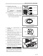
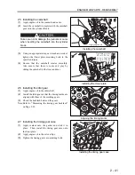
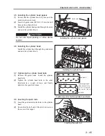
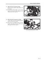
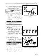
2.12 Installing the rear plate
(1)
Install a new rear plate gasket.
(2)
Install the rear plate, aligning it with the dowel
pins. Tighten the retaining bolts to the
specified torque.
Note: Install the rear plate complete with the starter.
This will facilitate the subsequent reassembly.
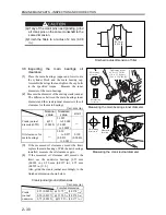
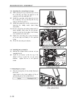
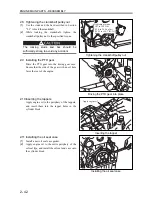
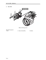
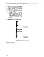
2.13 Installing the flywheel housing
Install the flywheel housing, aligning it with the
knock pins. Tighten the retaining bolts evenly.
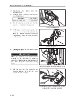
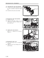
Note: Replace the knock pins with new parts if the
knock pins are worn or if a new flywheel
housing is being installed.
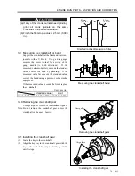
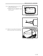
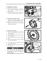
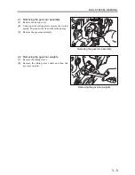
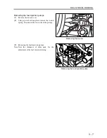
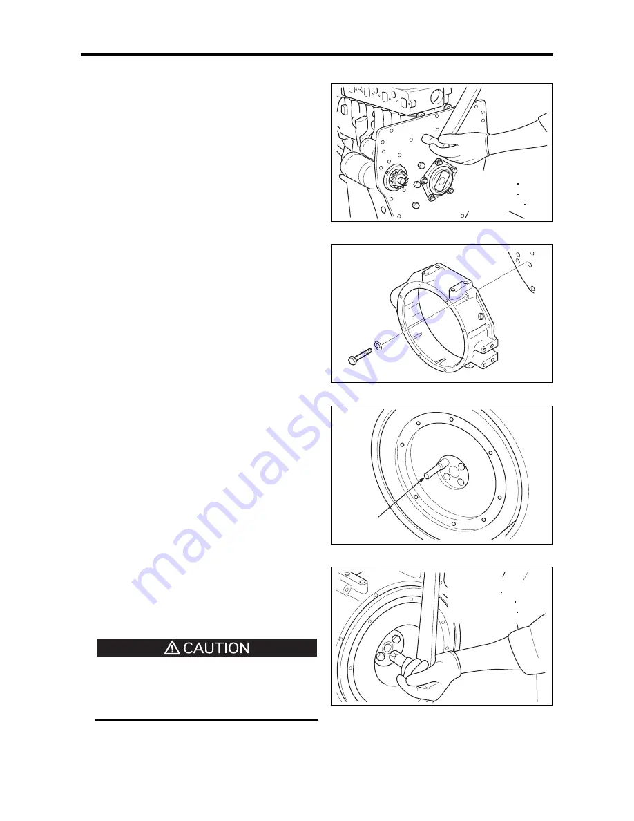
2.14 Installing the flywheel
(1)
Screw in a safety stud (M12
×
1.25) into one of
the flywheel retaining bolt holes at the rear end
of the crankshaft.
(2)
Insert the flywheel through the safety stud and
onto the crankshaft.
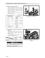
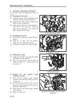
(3)
Loosely tighten the three flywheel retaining
bolts.
(4)
Replace the safety stud with the 4th retaining
bolt, and loosely tighten it.
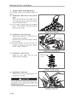
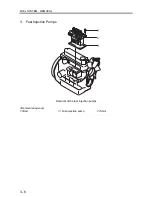
(5)
Using a torque wrench or other similar tool, lock
the crankshaft pulley nut.
(6)
Tighten the flywheel retaining bolts to the
specified torque.
The person who locks the crankshaft pulley
nut should do so with extreme care.
Communicate with each other closely to
prevent accidents.
Installing the rear plate
Installing the flywheel housing
Installing the flywheel
Tightening the flywheel bolts
Tightening torque:
53.9 to 73.5 N m
(5.5 to 7.5 kgf m)
[39.8 to 54.2 lbf ft]
Tightening torque:
127 to 137 N m
(13.0 to 14.0 kgf m)
[94.0 to 101.3 lbf ft]
Safety stud
Summary of Contents for diesel engines
Page 5: ......
Page 33: ...SERVICE STANDARDS 1 20 ...
Page 34: ...1 General Tools 1 22 2 Special Tools 1 23 TOOLS LIST ...
Page 37: ...TOOLS LIST 1 24 ...
Page 41: ...OVERHAUL TIMING 1 28 ...
Page 46: ......
Page 47: ......
Page 61: ...ENGINE MAIN PARTS DISASSEMBLY 2 16 ...
Page 99: ...FUEL SYSTEM REMOVAL 3 8 ...
Page 115: ...FUEL SYSTEM DISASSEMBLY INSPECTION AND REASSEMBLY 3 24 ...
Page 119: ...FUEL SYSTEM INSTALLATION 3 28 2 Governor Installing the governor Installation sequence ...
Page 123: ...FUEL SYSTEM INSTALLATION 3 32 ...
Page 131: ...OIL SYSTEM DISASSEMBLY INSPECTION AND REASSEMBLY 4 8 ...
Page 143: ...COOLING SYSTEM DISASSEMBLY INSPECTION AND REASSEMBLY 5 8 ...
Page 150: ......
Page 151: ......
Page 153: ...INLET AND EXHAUST SYSTEMS REMOVAL 6 4 ...
Page 159: ...INLET AND EXHAUST SYSTEMS INSTALLATION 6 10 ...
Page 160: ...1 Starter 7 2 2 Alternator 7 3 3 Stop Solenoid 7 4 4 Glow Plug 7 5 ELECTRICAL SYSTEM REMOVAL ...
Page 165: ...ELECTRICAL SYSTEM REMOVAL 7 6 ...
Page 189: ...ELECTRICAL SYSTEM INSTALLATION 7 30 ...
Page 207: ...MISCELLANEOUS 9 4 ...


