
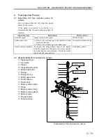
ENGINE MAIN PARTS - REASSEMBLY
2 - 44
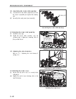
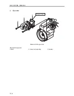
3. Cylinder Head, Valve Mechanism
To reassembly, follows the disassembly sequence in
reverse.
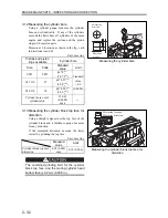
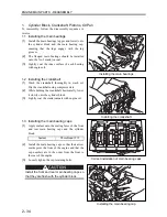
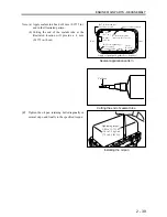
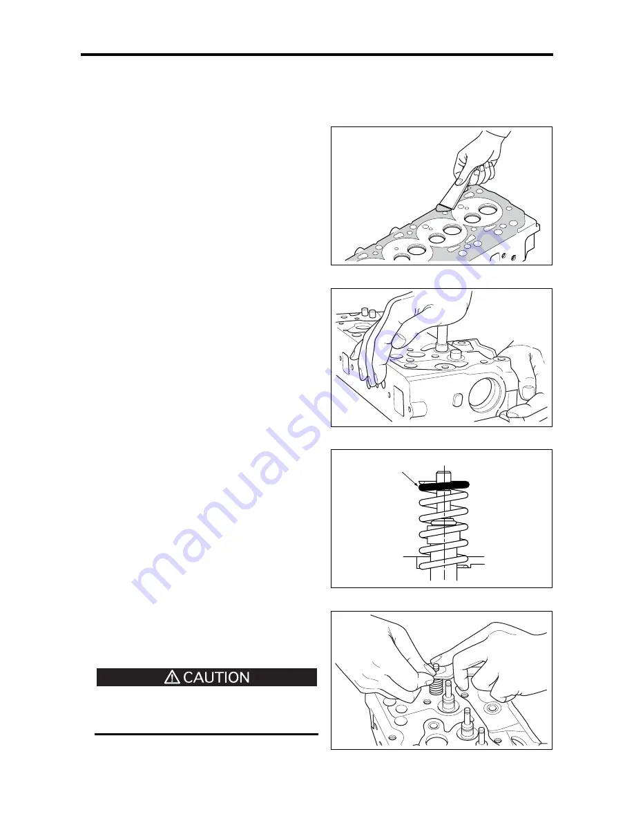
3.1 Cleaning the bottom face of the cylinder
head
Scrape off any gasket from the mating faces of
the cylinder head and the cylinder block, taking
care not to damage the faces.
Note: Use a scraper to roughly remove the remaining
gasket. Then, using an oil stone and engine oil,
polish away fine residue.
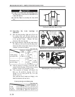
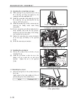
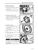
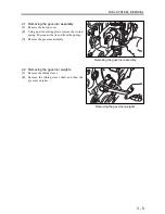
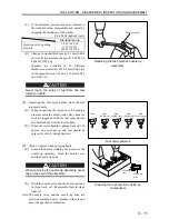
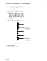
3.2 Installing the valve stem seals
Using a box wrench No. 12, install the valve
stem seal on the valve guide.
Ensure that the seal has been correctly installed
the valve guide.
Note: Incorrectly installed stem seals will lead to oil
leaking down through the seal-to-guide gap and
into the combustion chamber.
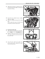
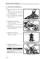
3.3 Installing the valve springs
Install the valve spring with the white
enamel-coated end facing up.
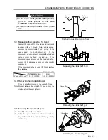
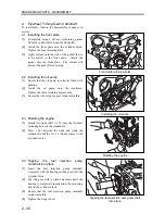
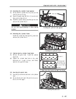
3.4 Installing the valve locks
Install the valve lock by compressing the valve
spring using a valve lifter.
Do not compress the valve spring too hard as
the bottom of the retainer may contact and
damage the stem seal.
Removing the old gasket
Inserting the valve stem seal
Installing the valve springs
Installing the valve lock
Box wrench No. 12
White enamel
coating
Summary of Contents for diesel engines
Page 5: ......
Page 33: ...SERVICE STANDARDS 1 20 ...
Page 34: ...1 General Tools 1 22 2 Special Tools 1 23 TOOLS LIST ...
Page 37: ...TOOLS LIST 1 24 ...
Page 41: ...OVERHAUL TIMING 1 28 ...
Page 46: ......
Page 47: ......
Page 61: ...ENGINE MAIN PARTS DISASSEMBLY 2 16 ...
Page 99: ...FUEL SYSTEM REMOVAL 3 8 ...
Page 115: ...FUEL SYSTEM DISASSEMBLY INSPECTION AND REASSEMBLY 3 24 ...
Page 119: ...FUEL SYSTEM INSTALLATION 3 28 2 Governor Installing the governor Installation sequence ...
Page 123: ...FUEL SYSTEM INSTALLATION 3 32 ...
Page 131: ...OIL SYSTEM DISASSEMBLY INSPECTION AND REASSEMBLY 4 8 ...
Page 143: ...COOLING SYSTEM DISASSEMBLY INSPECTION AND REASSEMBLY 5 8 ...
Page 150: ......
Page 151: ......
Page 153: ...INLET AND EXHAUST SYSTEMS REMOVAL 6 4 ...
Page 159: ...INLET AND EXHAUST SYSTEMS INSTALLATION 6 10 ...
Page 160: ...1 Starter 7 2 2 Alternator 7 3 3 Stop Solenoid 7 4 4 Glow Plug 7 5 ELECTRICAL SYSTEM REMOVAL ...
Page 165: ...ELECTRICAL SYSTEM REMOVAL 7 6 ...
Page 189: ...ELECTRICAL SYSTEM INSTALLATION 7 30 ...
Page 207: ...MISCELLANEOUS 9 4 ...


