


14-1
CONTENTS
14109000208
. . . . . . . . . . . . . . . . . .
. . . . . . . . . . . . . . . . .
. . . . . . . . . . . . . . . . . . . . . . . . . . . . . . .
. . . . . . . . . . . . . . . . . . . . . . . . . . . . . . . .
. . . . . . . . . . . . . . . . . . . . . . . . . . . .
. . . . . . . . . . . . . . . . . . . . . . .
. . . . . . . . . . . . . . . . . . . . .
Engine Coolant Leak Checking
9
. . . . . . . . . . . . . . . .
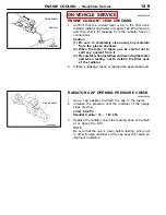
Radiator Cap Opening Pressure
Check
9
. . . . . . . . . . . . . . . . . . . . . . . . . . . . . . . . . . . . . . .
Engine Coolant Replacement
10
. . . . . . . . . . . . . . . . .
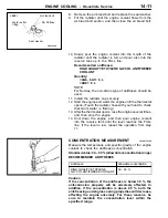
Concentration Measurement
11
. . . . . . . . . . . . . . . . . .
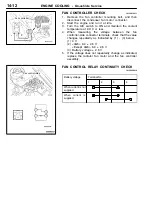
Fan Controller Check
12
. . . . . . . . . . . . . . . . . . . . . . . .
Fan Control Relay Continuity Check
12
. . . . . . . . . .
. . . . . . . . . . . . . . . . . . . . . . . . . . .
. . . . . . . . . . . . . . . . . . . . . . . . . . . . . . . .
. . . . . . . . . . . . . . . . . . . . . . . . . . . . . . . .
. . . . . . . . . . . . . . . . . . . . . . . . . . . . . . . .
. . . . . . . . . . . . . . . . . . . . . . . . . . . . . . .
Summary of Contents for Engine cooling
Page 26: ...NOTES ...


