


ENGINE COOLING -
Troubleshooting
14-4
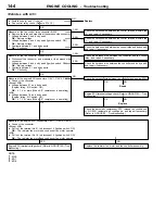
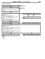
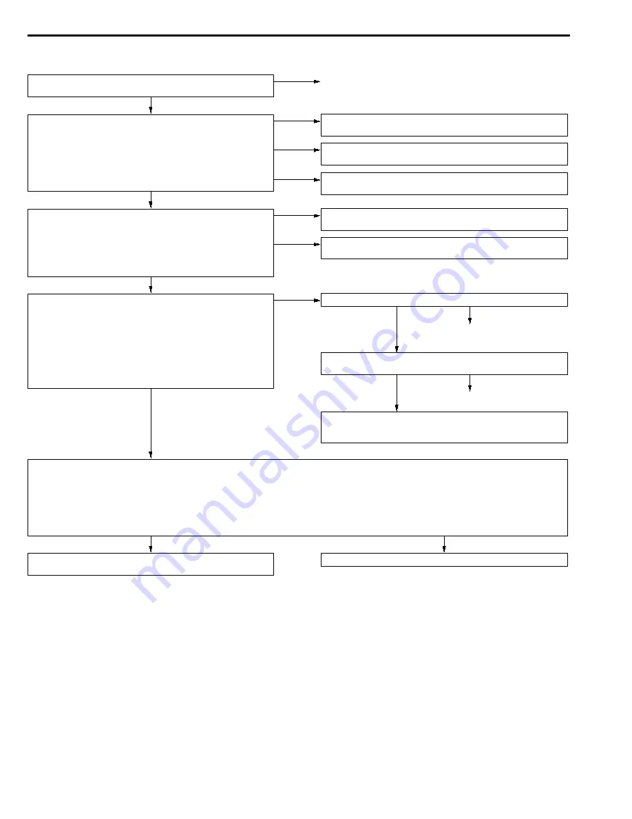
<Vehicles with A/C>
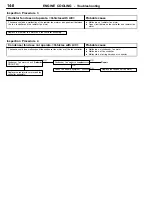
OK
1. NG
Check the harness wire between fan control relay and fusible link
(4), and repair if necessary.
2. NG
Check the harness wire between fan control relay and fusible link
(7), and repair if necessary.
3. NG
Check the harness wire between fan control relay and body earth,
and repair if necessary.
OK
NG
Repair
OK
NG
Replace
Check the automatic compressor-ECU <manual air conditioner>
or A/C-ECU <automatic air conditioner>, and repair if necessary.
(Refer to GROUP 55 - Troubleshooting.)
YES
NO
Engine-ECU terminal voltage check (Refer to GROUP 13A - Trou-
bleshooting.)
Replace the radiator fan motor and fan controller assembly.
NOTE
*1: 4G6
*2: 6A1
*3: 4D6
OK
Measure at the engine-ECU connectors C-34*1, C-33*2, C-53*3.
D
Connect the connector.
<Except 4D6>
D
Pull out the terminal No.21 to disconnect it (Ignition switch: ON)
OK:
The radiator fan motor and condenser fan motor operate.
<4D6>
D
Pull out the terminal No.18 to disconnect it (Ignition switch: ON)
OK:
The radiator fan motor and condenser fan motor operate.
Engine-ECU terminal voltage check (Refer to GROUP 13A - Trou-
bleshooting.)
OK
Measure at the engine-ECU connectors C-34*1, C-33*2, C-53*3.
D
Connect the connector.
<Except 4D6>
D
Voltage between 21 and body earth
(Engine: idling, A/C switch: ON)
OK:
0.7 V or more (When A/C compressor is operating)
<4D6>
D
Voltage between 18 and body earth
(Engine: idling, A/C switch: ON)
OK:
0.7 V or more (When A/C compressor is operating)
NG
Check the harness wire between fan controller and engine-ECU.
OK
1. NG
Check the harness wire between fan controller and fan control
relay, and repair if necessary.
2. NG
Check the harness wire between fan controller and body earth,
and repair if necessary.
Measure at the fan controller connector A-22.
D
Disconnect the connector, and measure at the harness side
connector.
1. Voltage between 3 and body earth (Ignition switch: ON)
OK:
Battery voltage
2. Continuity between 1 and body earth
OK:
Continuity
Measure at the fan control relay connector B-20X.
D
Remove the relay, and measure at the harness side connector.
1. Voltage between 4 and body earth
OK:
Battery voltage
2. Voltage between 3 and body earth (Ignition switch: ON)
OK:
Battery voltage
3. Continuity between 1 and body earth
OK:
Continuity
D
Fusible links (4) and (7) check
D
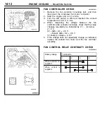
Fan control relay check (Refer to P.14-12.)
NG
Replace
Summary of Contents for Engine cooling
Page 26: ...NOTES ...


