F940GOT-SWD-E/LWD-E
Installation, Wiring and General Specifications 2.
2-27
•
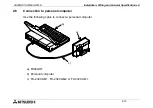
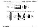
Connect the GOT to the computer link unit (PLC) as shown below.
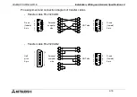
< For RS-422 communication >
< For RS-232C communication > The connection cable F2-232CAB is also available.
D-sub
(male)
9-pin
Terminal
block
GOT
side
Computer link
unit side
(PLC side)
RDA
RDB
SDA
SDB
SG
5
4
3
2
1
9
8
7
6
1
6
2
7
5
D-sub
25-pin
D-sub
(female)
9-pin
GOT
side
Computer link
unit side
(PLC side)
5
4
3
2
1
9
8
7
6
13
12
11
10
9
8
7
6
5
4
3
2
1
25
24
23
22
21
20
19
18
17
16
15
14
FG
SD
RD
RS
CS
DSR
SG
CD
DTR
1
2
3
7
8
6
5
4
1
2
3
4
5
6
7
8
20
Summary of Contents for F940
Page 1: ...HARDWARE MANUAL F940GOT SWD E LWD E ...
Page 6: ...F940GOT SWD E LWD E iv Memo ...
Page 28: ...F940GOT SWD E LWD E INTRODUCTION 1 1 20 ...
Page 84: ...F940GOT SWD E LWD E Startup 3 3 18 ...
Page 88: ...F940GOT SWD E LWD E Extension Module 4 4 4 ...
Page 94: ...F940GOT SWD E LWD E Maintenance 5 5 6 ...
Page 108: ...F940GOT SWD E LWD E Additional Functions in V3 10 or later 8 8 2 ...
Page 110: ...F940GOT SWD E LWD E Additional Functions in V4 00 or later 9 9 2 ...

