Introduction 1
1-1
1.
Introduction
This section describes the product configuration and the system configuration of the graphic
operation terminal.
1.1
Outline
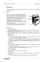
The graphic operation terminal (hereafter abbreviated to
GOT) is to be mounted on the face of a control panel or
operations panel, and connected to the programming
port of an FX or A series programmable controller (here-
after abbreviated to PLC (except the A0J2))
Various devices can be monitored and PLC data
changed through the screens of the GOT.
There are several display screens built-in to the GOT
which offer various functions. In addition user defined
screens can be created.
The user defined screens and the built-in screens (sys-
tem screens) have the following respective functions.
User screens
•
Screen display function
The following functions can be assigned to each screen. Also the available screens can be
limited using the security function.
Both software packages, FX-PCS-DU/WIN-E (V2.00) available for DU, and the SW
o
D5C-
GOTRE-PACK ("
o
" indicates a numeric not less than "1".) available for GOT can be used to
create user screens.
Display function
-
Up to 500 user defined screens can be displayed. In screen creation, two or more
screens can be overlaid or changed over arbitrarily.
-
Simple graphics such as straight lines, circles and rectangles can be displayed, along
with numerics and English, Japanese, Chinese and Korean text. Also bitmaps can be
imported and displayed on screen the F940GOT-SED-E can display screen components
in 8 colors.
Monitor function
-
Set values and current values of word devices in the PLC can be displayed in numerics
or bar graphs for monitoring.
-
The specified range of the screen components can be displayed in reverse in accor-
dance with the ON/OFF status of bit devices in the PLC.
Data change function
-
The numeric data being monitored can be changed.
Switch function
-
By manipulating the operation keys in the GOT, bit devices in the PLC can be set to ON
and OFF.
The display panel face can be assigned as touch keys to offer the switch function.
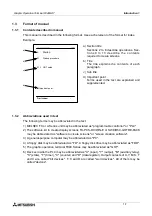
FX or
A Series PLC
Program
connector
GOT main body
Graphic Operation Terminal F940GOT
Summary of Contents for F940GOT-LWD-E
Page 1: ...OPERATION MANUAL F940GOT SWD E F940GOT LWD E...
Page 4: ...Graphic Operation Terminal F940GOT 2...
Page 6: ...Graphic Operation Terminal F940GOT 4...
Page 8: ...Graphic Operation Terminal F940GOT 6...
Page 14: ...Graphic Operation Terminal F940GOT Contents vi...
Page 104: ...Graphic Operation Terminal F940GOT Alarm Mode 6 6 12...
Page 148: ...Graphic Operation Terminal F940GOT Creation of Display Screens 9 9 30...
Page 228: ...Graphic Operation Terminal F940GOT Changeover of Display Screen FX PCS DU WIN E 11 11 18...


