Graphic Operation Terminal F940GOT
Introduction 1
1-2
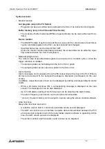
System screens
•
Monitor function
List program (only in the FX Series)
-
Programs can be read, written and monitored in the form of an instruction list program.
Buffer memory (only in the FX
2N
and FX
2NC
Series)
-
The contents of buffer memories (BFMs) of special blocks can be read, written and mon-
itored.
Device monitor
-
The ON/OFF status of each device and the set value and the current value of each timer,
counter and data register in the PLC can be monitored and changed.
-
Specified bit devices can be forced ON or OFF.
Unlike the monitor function described previously, the screen data can be edited by input-
ting a desired device No. from the keyboard.
•
Data sampling function
The current value of specified data registers are acquired in a constant cycle or when the
trigger condition is satisfied.
-
The sampling data can be displayed in the form of list or graph.
-
The sampling data can be output to a printer in the form of list.
•
Alarm function
Alarm messages can be assigned to up to 256 consecutive bit devices in the PLC. When a
bit device becomes ON, the assigned message is displayed (overlapped) on the user
screen.
In addition, a specified user screen can be displayed by setting a corresponding bit device
to ON.
-
When a bit device becomes ON, a corresponding message is displayed on the user
screen. The message list can be also displayed.
-
Up to 1,000 alarms (turning ON of bit devices) can be stored as the alarm history.
-
The alarm frequency each device can be stored as historical data.
* As to 2), the alarm history can be output to a printer using the screen creation software.
•
Other functions
Many other functions are built in.
-
A real-time clock is built in, current time and data can be set and displayed.
-
The GOT can function as an interface to enable data communication between the PLC
and a personal computer in which the relay ladder creation software is operating. At this
time, the GOT screen can also be displayed.
-
The screen contrast and the buzzer sound volume can be adjusted.
Summary of Contents for F940GOT-LWD-E
Page 1: ...OPERATION MANUAL F940GOT SWD E F940GOT LWD E...
Page 4: ...Graphic Operation Terminal F940GOT 2...
Page 6: ...Graphic Operation Terminal F940GOT 4...
Page 8: ...Graphic Operation Terminal F940GOT 6...
Page 14: ...Graphic Operation Terminal F940GOT Contents vi...
Page 104: ...Graphic Operation Terminal F940GOT Alarm Mode 6 6 12...
Page 148: ...Graphic Operation Terminal F940GOT Creation of Display Screens 9 9 30...
Page 228: ...Graphic Operation Terminal F940GOT Changeover of Display Screen FX PCS DU WIN E 11 11 18...

