Graphic Operation Terminal F940GOT
Creation of Display Screens (FX-PCS-DU/WIN-E) 10
10-29
10.4.11 Image Indicator
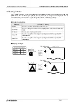
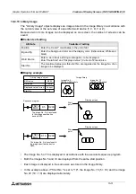
The "Image Indicator" object changes over the displayed image in accordance with the ON/
OFF status of a bit device (X, Y, M, S, T or C) in the PLC. Images to be displayed can be
entered directly or selected using the image No. stored in the image library.
u
u
u
u
Contents of setting
u
u
u
u
Display example
Attribute
Contents of setting
Position
Enter the X and Y coordinates in the unit of dot.
Bg and Fg
Enter the background color and the display color. (Initial values: White and
black)
Bit Device
Enter a bit device to be referred to.
Image Off
Enter the image No. of an image to be displayed while the specified bit
device is OFF.
Image On
Enter the image No. of an image to be displayed while the specified bit
device is ON.
"Image Indicator" object
Display screen
Display start
point
Display start
point
While M0 is
ON, the
image No.
20 is
displayed.
While M0 is
ON, the
image No.
30 is
displayed.
Image library
Image No. 20
50 W
×
50 H dots
Image No. 30
100 W
×
100 H dots
Bit Device
Image On
Image Off
M0
20
30
Summary of Contents for F940GOT-LWD-E
Page 1: ...OPERATION MANUAL F940GOT SWD E F940GOT LWD E...
Page 4: ...Graphic Operation Terminal F940GOT 2...
Page 6: ...Graphic Operation Terminal F940GOT 4...
Page 8: ...Graphic Operation Terminal F940GOT 6...
Page 14: ...Graphic Operation Terminal F940GOT Contents vi...
Page 104: ...Graphic Operation Terminal F940GOT Alarm Mode 6 6 12...
Page 148: ...Graphic Operation Terminal F940GOT Creation of Display Screens 9 9 30...
Page 228: ...Graphic Operation Terminal F940GOT Changeover of Display Screen FX PCS DU WIN E 11 11 18...

